
Grading System

a grading system and grading technology, applied in the field of earth moving equipment, can solve the problems of limited ground cutting ability, insufficient control of the blade to permit accurate automated control, and limit the ability to achieve the intended goal of fine grading, so as to improve stiffness, improve performance, and reduce bounce

Active Publication Date: 2021-11-18
SC GRADE LLC
View PDF0 Cites 0 Cited by
  • Summary
  • Abstract
  • Description
  • Claims
  • Application Information

AI Technical Summary

Benefits of technology

The present patent provides a grading system for track vehicles that overcomes shortcomings of prior art systems. The grading system is able to utilize automated control and achieve better performance, with finishing within a few inches of the grading site plan. The system includes a grading blade assembly and a cutting element assembly that can fine grade areas with hard ground or debris. The system is compact and efficient, with a short distance between the front of the vehicle and the blade, and can be used with the optional cutting element assembly. The system also reduces bouncing and straying of the blade, and can be used with automated control. Overall, the grading system provides better performance, efficiency, and a higher quality slab, reducing waste and achieving the goal of providing a high quality slab, finishing the fine grading well within the required site plan specifications.

Problems solved by technology

With known grading systems, this effort often results in finishing within ⅜″ or ½″ of the grading site plan.
It would be particularly advantageous to be able to use an automated grade control system on a fine grader, but typical skid steer vehicles and grading blade assemblies used for fine grading are not equipped to sufficiently control a blade to permit accurate automated control.
There are some specialized grading systems that are capable of employing automation, but the structures unfortunately have undesirable bounce or instability of the grading system and little downward pressure, which results in very limited ground cutting ability and ultimately limits the ability to achieve the intended goal in fine grading.
The limitations can be due to the extent to which a grading system extends forward from the vehicle, the use of forward support wheels and / or the mounting and controls, which typically include vertically movable arms on the vehicle and hydraulic actuators to control the pitch of a quick attach mounting plate.
To do so, the known vehicles that have a level blade with the vertically movable arms of a vehicle against a lower stop must use a pitch control on the vehicle to tilt the quick attach mounting plate forward so as to extend the lower edge of the grading blade below the height of the vehicle tracks, however, this causes the pivot axis of the grading blade to be significantly tilted, interfering with the ability to use a grading control system.
There have been developments that include adding a stop bracket that is engaged by use of the hydraulic actuators that control the pitch of the quick attach mounting plate, but this only goes so far in trying to control the bounce introduced in a grading blade assembly where the blade is located well forward of the vehicle, the vehicle arms are still vertically movable, the quick attach mounting introduces undesirable movement, and the hydraulic actuators that control the pitch of the quick attach mounting plate can still bounce against the stop bracket.
Such areas often require digging and removal by use of heavy duty digging equipment, followed by delivery of new soil to fill as needed because known grading systems are not capable of dealing with such solid ground variations or large chunks of hard dirt that may have been left by a dirt contractor.
To date, fine grading systems are not equipped to deal with cutting such hard ground environments.
Thus, existing fine grading systems include disadvantages that limit grading performance and that do not enable a fine grading assembly to work through hard ground without extensive intervention from other equipment.

Method used


Image

  • Grading System
  • Grading System
  • Grading System

Examples


Embodiment Construction

[0031]Referring generally to FIGS. 1-13, it will be appreciated that grading systems of the present disclosure generally may be embodied in numerous configurations. Indeed, the teachings within this disclosure present embodiments that provide significant advantages over prior art grading systems, and in some instances with optional alternative structures.

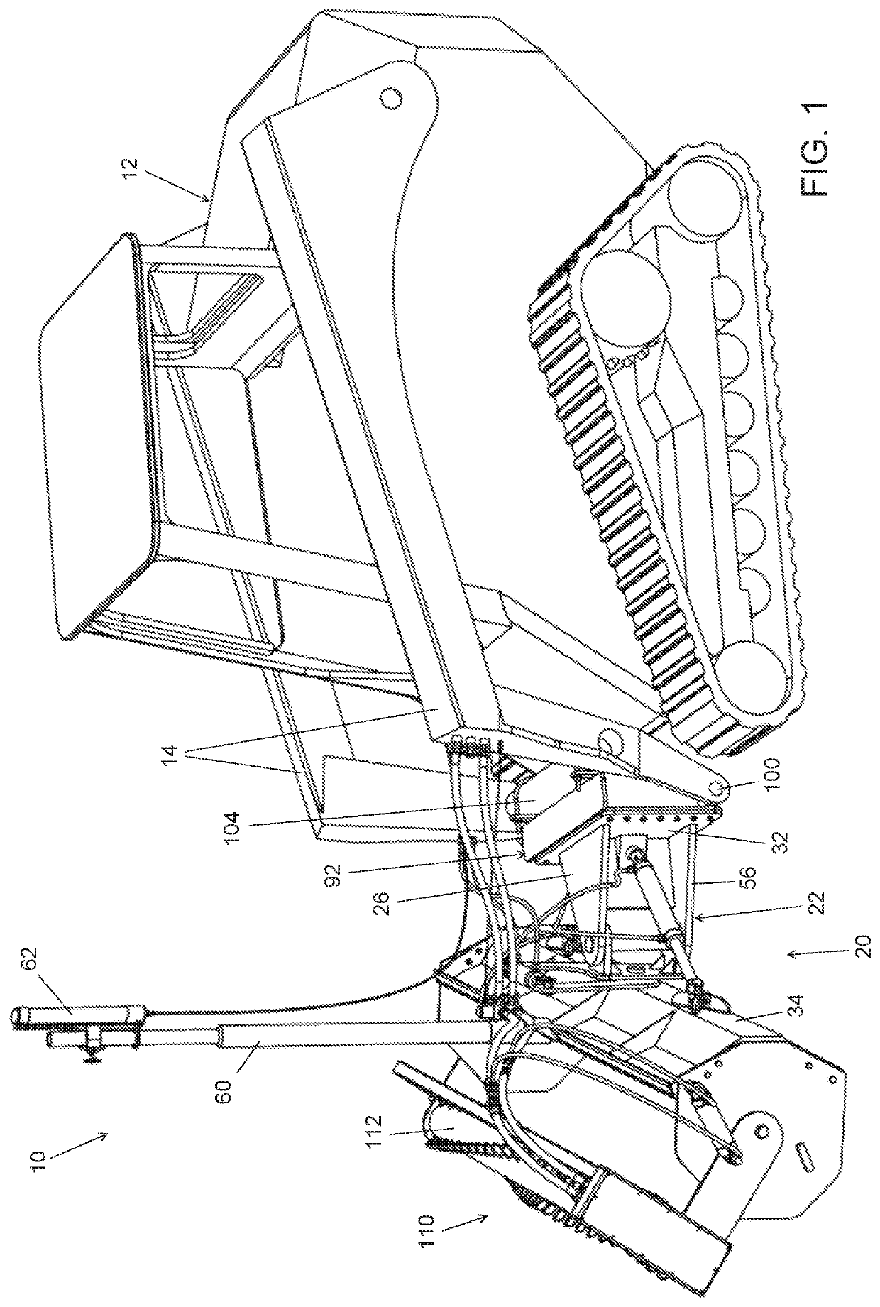
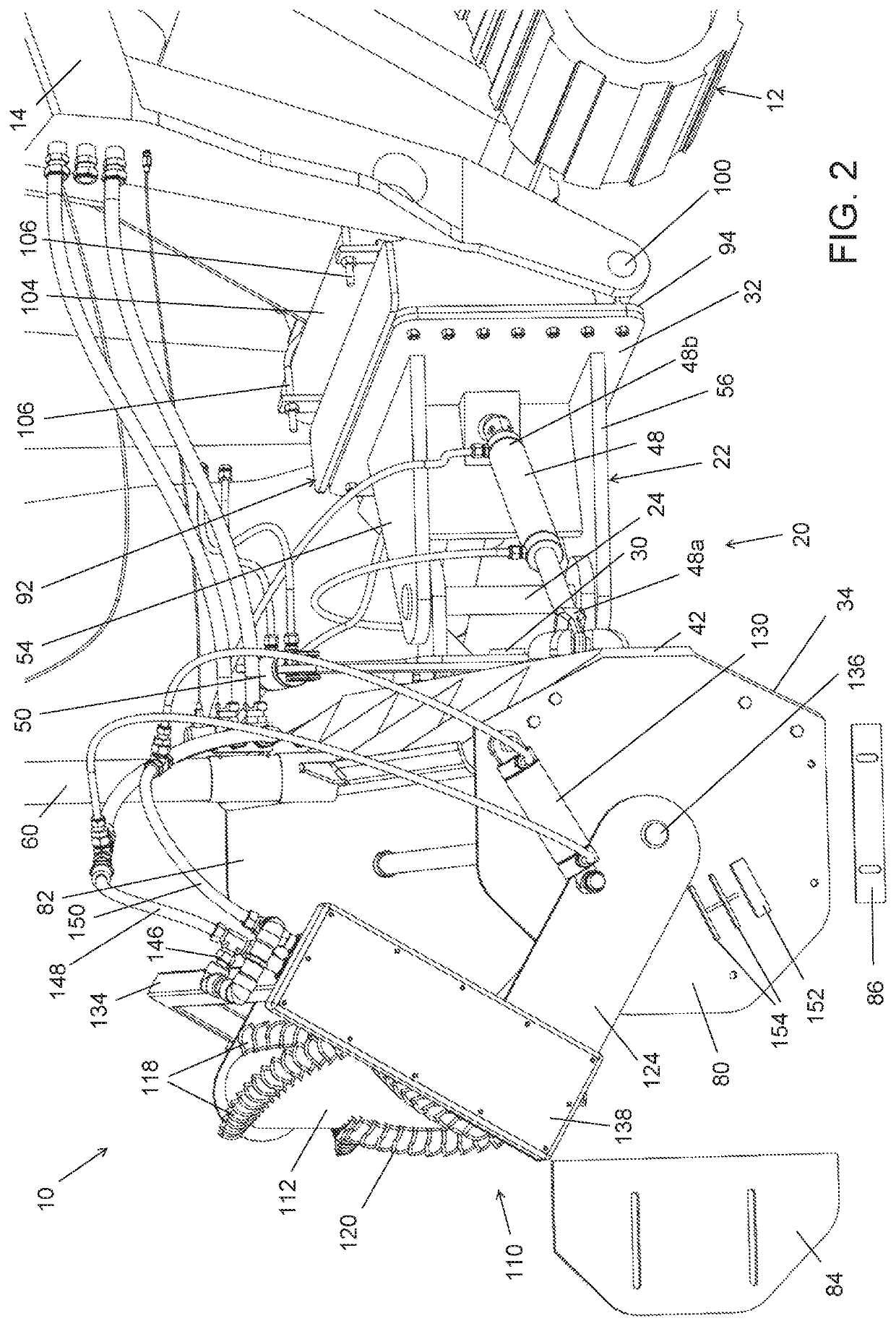
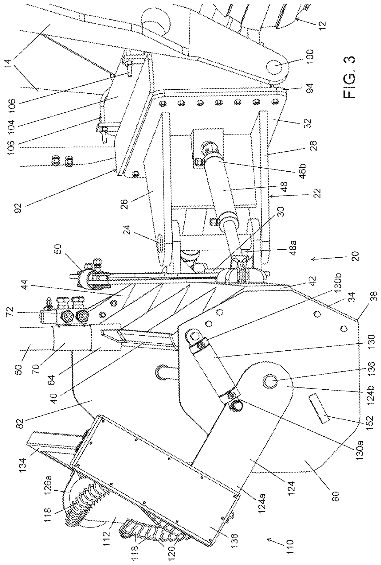
[0032]FIGS. 1-12 show one or more variations of a first example embodiment of a grading system 10 for connection to a vehicle 12 having vertically movable arms 14. The vehicle 12 preferably is constructed as a track vehicle, such as a skid steer vehicle that may be available from a number of different manufacturers of commercial construction equipment. It will be appreciated that the grading system 10 may be mounted on a wheeled vehicle, although this would not be quite as desirable as mounting on a track vehicle, because a wheeled vehicle generally would not be steady on the ground as a track vehicle.

[0033]The grading system 10 sho...


PUM


Abstract

A grading system for connection to a vehicle having vertically movable arms, the grading system including a grading blade assembly having a frame having a first pivot extending upward, a second pivot extending forward, a blade connected to the frame via the first pivot and the second pivot, a blade yaw actuator and a blade roll actuator, wherein the frame is configured to have the first pivot extend substantially vertically and the second pivot extend substantially longitudinally when the grading blade assembly is connected to the vehicle and the blade and vehicle are in a level position on a ground surface and the vertically movable arms of the vehicle are in a first raised position above a lowest most position.

Description

BACKGROUNDField of the Invention[0001]The present invention generally relates to earth moving equipment, and more particularly to a grading system for use on a vehicle.Description of the Related Art[0002]Earth moving equipment is available in different forms and for different purposes. Once excavation and concrete contractors have completed major work, which may include excavating and / or pouring a foundation for a structure, such as a commercial building or house, a dirt contractor works to build up or cut down the dirt pad or ground on the site, which may include the area around and inside of a structure. The dirt contractor is tasked with bringing the site to within 1 / 10 of a foot of the specifications on a grading site plan. Following the work by a dirt contractor, a fine grading contractor is brought in to move dirt and / or gravel with a goal in fine grading to achieve the highest quality slab and to keep the waste factor as little as possible. With known grading systems, this ef...

Claims


Application Information

Patent Timeline
IPC IPC(8): E02D3/032E02F3/78
CPCE02D3/032E02F3/783E02F3/847
Inventor STOCKS, BO JASON
Owner SC GRADE LLC
Learn More