
Throttle Body Spacing Block with Individual Rings in Grooved Aperture for Manipulating Airflow in Internal Combustion Engines

a technology of internal combustion engine and spacing block, which is applied in the direction of combustion engine, combustion-air/fuel-air treatment, charge feed system, etc., can solve the problems of reducing the efficiency of combustion, so as to achieve easy and efficient manufacturing and marketing, increase the distance, and increase the distan

Inactive Publication Date: 2021-11-18
PATTERSON LARRY +2
View PDF0 Cites 0 Cited by
  • Summary
  • Abstract
  • Description
  • Claims
  • Application Information

AI Technical Summary

Benefits of technology

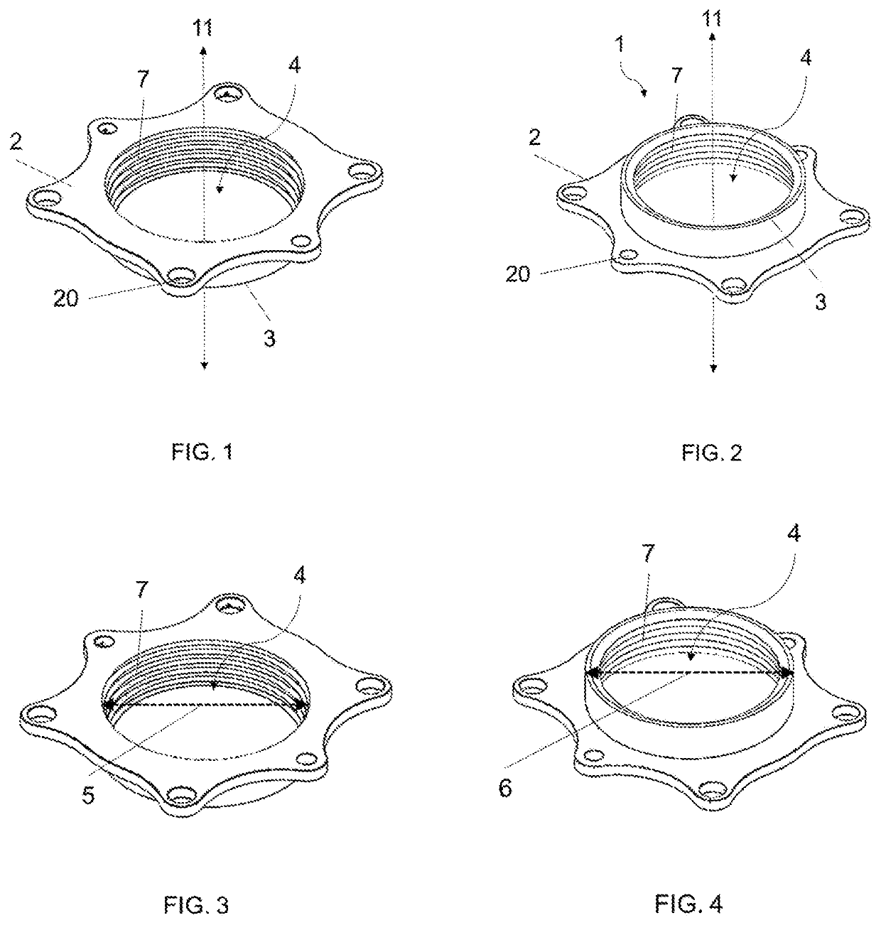
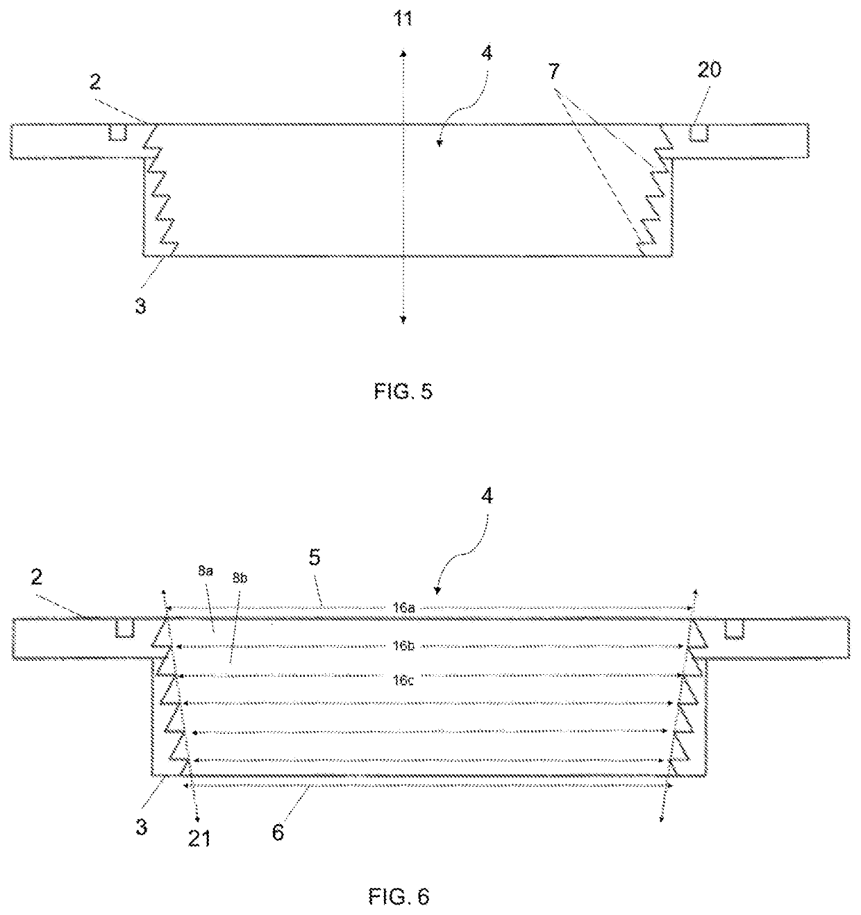
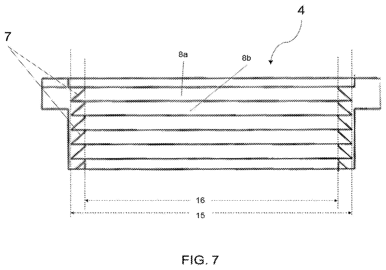
The present invention is a new and improved throttle body spacing block for internal combustion engines that helps increase combustion efficiency, reduce harmful emissions, and improve fuel efficiency. The invention has specially designed grooved apertures that act to increase air velocity and create an air vortex, which leads to a more oxygenated fuel supply, resulting in more efficient fuel combustion. This device can be used with various engines and can be manufactured and marketed easily. Additionally, the invention can be retrofit upon existing intake manifolds of engines.

Problems solved by technology

Diesel fuel produces various harmful emissions when it is burned.
For this reason, diesel-fueled vehicles are major sources of harmful pollutants.
While the EPA has established various fuel standards to help reduce the effects of these pollutants on the environment, diesel fuel still contributes to air pollution.
Most products on the market today, however, are designed to improve air quality only after the harmful emissions are created within the engine.
But these devices do not provide any means by which to directly increase the velocity of the air charge or to turbinate the air charge as it passes through the aperture.

Method used


Image

  • Throttle Body Spacing Block with Individual Rings in Grooved Aperture for Manipulating Airflow in Internal Combustion Engines
  • Throttle Body Spacing Block with Individual Rings in Grooved Aperture for Manipulating Airflow in Internal Combustion Engines
  • Throttle Body Spacing Block with Individual Rings in Grooved Aperture for Manipulating Airflow in Internal Combustion Engines

Examples


Embodiment Construction

[0027]Generally speaking, the present invention is directed to a device for reducing the harmful emissions generated and emitted by combustion engines. The device may generally be described as a throttle body spacing block, as known in the art. In very general terms the present invention is a device that disturbs or manipulates the amount air flow in the engine, causing the air to flow in a different pattern and causing a heterogenous mixture to be more efficient at ignition. As noted above, while the present invention is suitable for use with a variety of different engine types, the invention may be particularly useful for use with diesel engines. Diesel engines are forced air engines. Air will fill any space that is not taken by mass. Therefore, as air is forced into an engine, the hotter air (which is less dense) will be found on the outer diameter inside the air intake tube. Being less dense allows hotter air flow to not be as easily disrupted, but it is far more manipulated by ...


PUM


Abstract

A device for connecting to the intake manifold of an internal combustion engine, the device having at least one grooved aperture for manipulating airflow through the device as the airflow moves into the intake manifold of the engine. The grooved aperture consists of a series of concentric and parallel grooved sections, each section having a minor diameter and a major diameter and incrementally increasing diameters therebetween, such that each section forms a frustum, such that the length of the aperture has a grooved internal surface that provides structure for manipulating the airflow through the device.

Description

CROSS REFERENCE TO RELATED APPLICATIONS[0001]Not applicable.STATEMENT REGARDING FEDERALLY SPONSORED RESEARCH OR DEVELOPMENT[0002]Not applicable.BACKGROUND OF THE INVENTION[0003]Diesel fuel produces various harmful emissions when it is burned. For this reason, diesel-fueled vehicles are major sources of harmful pollutants. While the EPA has established various fuel standards to help reduce the effects of these pollutants on the environment, diesel fuel still contributes to air pollution. According to a 2018 study by the U.S. Energy Information Administration (EIA), diesel fuel consumption in the U.S. transportation sector accounted for about 24% of the total. U.S. transportation sector carbon dioxide emissions and about 9% of the total U.S. energy-related carbon dioxide emissions in 2018. Given the disastrous effects climate change is having on our planet, there have been many attempts through legislation and through innovation to reduce the amount of harmful pollutants emitted into ...

Claims


Application Information

Patent Timeline
IPC IPC(8): F02M35/10
CPCF02M35/10262Y02T10/12
Inventor PATTERSON, LARRYBROWN, JERRYPATTERSON, ADAM
Owner PATTERSON LARRY
Learn More