Vibration control system

a control system and vibration technology, applied in the direction of mechanical vibration separation, process and machine control, instruments, etc., can solve the problems of significant waste of effort, inability to create a system that literally reproduces the above, and limitations of vibration testers on specifications related to maximum velocity, etc., to achieve the effect of sufficient structur

Pending Publication Date: 2021-11-18
IMV
View PDF2 Cites 3 Cited by
  • Summary
  • Abstract
  • Description
  • Claims
  • Application Information

AI Technical Summary

Benefits of technology

[0011]In addition, in general, the vibration tester has limitations on specifications related to the maximum velocity, maximum displacement, and the like in addition to the maximum excitation force and maximum acceleration that can be output according to the basic specifications. In the case where the signal of the velocity or the displacement exceeds the maximum specification thereof even for a moment while the acceleration falls within the maximum specification thereof, a safety system is actuated at the moment, which possibly interrupts the test. In such a case, as long as a maximum peak value of the velocity or the displacement can rationally be controlled to a certain value or lower, it is possible to reliably avoid such a situation where the vibration exceeding a limit of such an amount occurs to stop the test regardless of a coincidence.
[0013]Similarly, in the case where displacement limitation is problematic, as long as a Gaussian acceleration random signal with the acceleration PSD requested for the test is achieved at a response point and a corresponding displacement signal can be reproduced as a non-Gaussian random signal, a peak value of which reliably falls within a certain value, the vibration test can be conducted without a possibility of discontinuation of the test caused by excess of the displacement limitation.
[0066]Any one or more of the functions / means described herein and / or in association with the accompanying figures / flowcharts, can be encoded as instructions, stored in the memory and executed by the CPU / processor. The instructions can also be part of a control program running on an operating system (OS) with any one or more of the inputs, determinations, calculations and / or outputs capable of being displayed on the display and / or output to the vibration generator. Applicant has expressed these functions / means in an understandable format that includes one or more of mathematical formula, in prose, and / or in a flow chart(s), and thus have provided sufficient structure.

Problems solved by technology

It is impossible to create a system that literally reproduces the above.
In addition, preparation for the extremely large peak, which hardly occurs, means a significant waste of effort.
In addition, in general, the vibration tester has limitations on specifications related to the maximum velocity, maximum displacement, and the like in addition to the maximum excitation force and maximum acceleration that can be output according to the basic specifications.
In the case where the signal of the velocity or the displacement exceeds the maximum specification thereof even for a moment while the acceleration falls within the maximum specification thereof, a safety system is actuated at the moment, which possibly interrupts the test.
However, in this system, the vibration of the test object is detected by an acceleration sensor.
However, the provisioning of many types of sensors is complicated and thus is not preferred.

Method used


Image

  • Vibration control system
  • Vibration control system
  • Vibration control system

Examples


first embodiment

1. First Embodiment

1.1 Functional Configuration

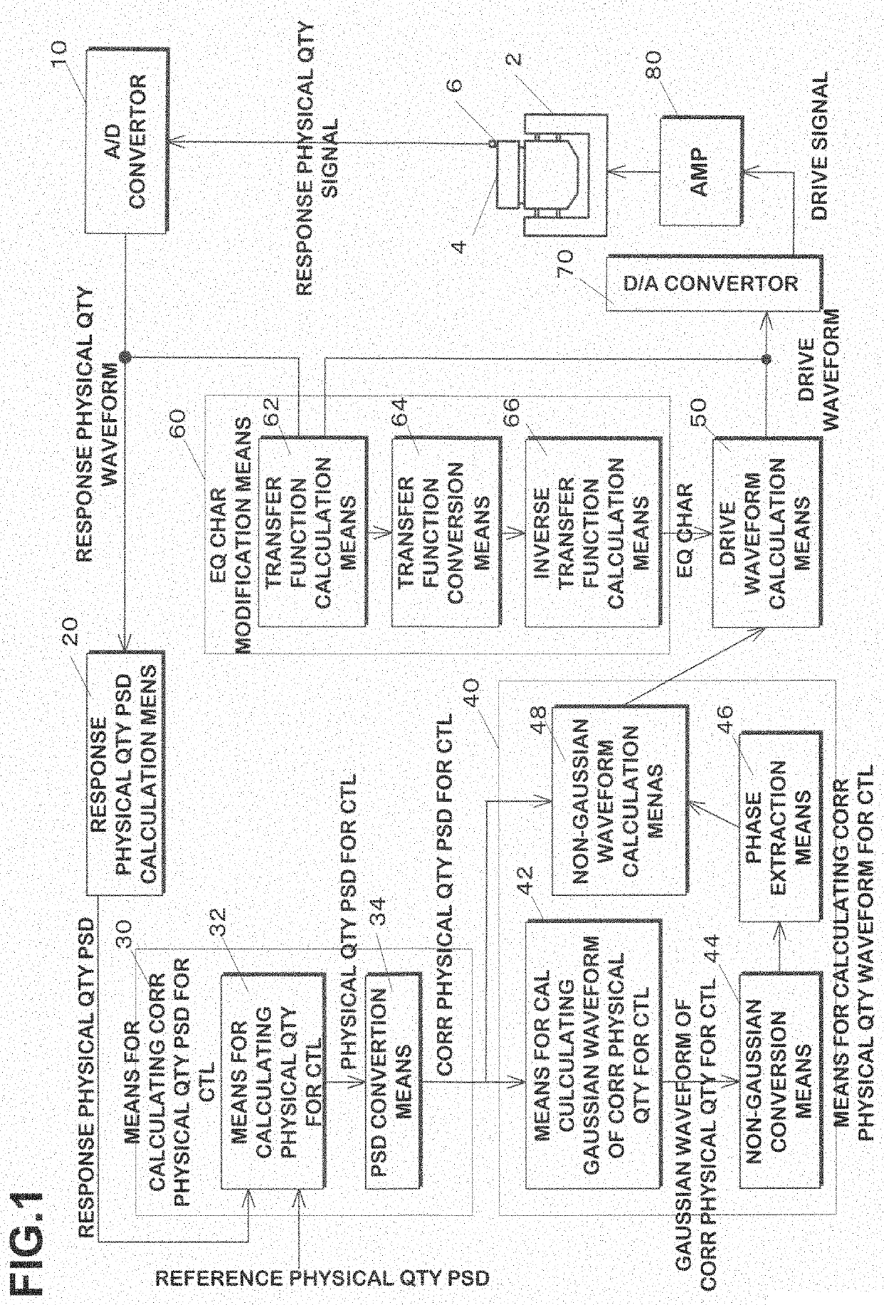
[0088]FIG. 1 is a functional configuration diagram of a vibration control system according to an embodiment of the present invention. In this embodiment, an amplifier 80, a vibration generator 2, a test object 4, and a vibration physical quantity detection sensor 6 are provided for control / evaluation by the vibration control system.

[0089]The test object 4 as a test target is placed on the vibration generator 2. The vibration physical quantity detection sensor 6 detects vibration of the test object 4 that is vibrated by the vibration generator 2. A displacement sensor, a velocity sensor, an acceleration sensor, a jerk sensor, or the like can be used as the vibration physical quantity detection sensor 6. A signal representing a response vibration physical quantity (a displacement signal, a velocity signal, an acceleration signal, a jerk signal, or the like) from the vibration physical quantity detection sensor 6 is converted into a respon...

second embodiment

2. Second Embodiment

2.1 Functional Configuration

[0168]FIG. 14 is a functional block diagram of a vibration control system according to another embodiment of the present invention. In this embodiment, control is executed such that the test object 4 vibrates in a manner that the waveform thereof matches a provided reference waveform. However, the dimension of the reference physical quantity is different from that of the response quantity that is detected by the sensor 6 attached to the test object 4. That is, the dimension of the reference corresponding physical quantity waveform differs from that of the response physical quantity waveform.

[0169]The drive waveform calculation means 50 calculates the drive waveform at least based on the provided reference corresponding physical quantity waveform and by using the equalization characteristics that is the reciprocal of the transfer function of the system. This drive waveform is provided to the vibration generator 2 via the D / A converter 7...


PUM


Abstract

A vibration control device, while applying Gaussian vibration that matches a target vibration physical quantity PSD to a test piece, makes a corresponding vibration physical quantity non-Gaussian. Using a response vibration physical quantity PSD and a target vibration physical quantity PSD, a control vibration physical quantity PSD calculation generates a control vibration physical quantity PSD for generating a drive signal. A PSD conversion converts the control vibration physical quantity PSD into a control corresponding vibration physical quantity PSD of another dimension. Using the control corresponding vibration physical quantity PSD, a control corresponding vibration physical quantity waveform calculation calculates a control corresponding vibration physical quantity waveform that is non-Gaussian. At least based on the control characteristics and the control corresponding vibration physical quantity waveform, a drive waveform calculation generates a next drive waveform such that vibration that matches the control corresponding vibration physical quantity waveform is applied to a test piece.

Description

CROSS-REFERENCE TO RELATED APPLICATIONS[0001]This application is a national stage application under 35 U.S.C. 371 of PCT Application No. PCT / JP2019 / 041305 having an international filing date of 21 Oct. 2019, which designated the United States, which PCT application claimed the benefit of Japanese Application No. 2019-015493, filed 31 Jan. 2019, each of which are incorporated herein by reference in their entirety.TECHNICAL FIELD[0002]One exemplary aspect of the present invention relates to a vibration control system for controlling vibration generated by a vibration generator in a vibration tester that is used to simulate a vibration environment.BACKGROUND ART[0003]A random vibration test is a method for experimentally verifying that performance, reliability, and durability of a test object satisfies a desired design by subjecting the test object to a prescribed vibration environment and checking a state of the test object during the vibration test or after the test. In general, a go...

Claims


Application Information

Patent Timeline
Patent Type & Authority Applications(United States)
IPC IPC(8): G01M7/02
CPCG01M7/022G01M7/025G05D19/02B06B1/0261G01H1/00
Inventor UENO, KAZUYOSHIYAMAUCHI, YOSHIKADONAKAUARA, YUJI
Owner IMV
Why Eureka
Try Eureka