
Optimizing pumping of variable viscosities via microtextured miniaturized tesla pump

a micro-textured, variable viscosity technology, applied in the direction of machines/engines, mechanical equipment, liquid fuel engines, etc., can solve the problems of increasing hemolysis, and affecting the pumping effect of the pumping devi

Active Publication Date: 2021-11-25
RGT UNIV OF MICHIGAN
View PDF0 Cites 0 Cited by
  • Summary
  • Abstract
  • Description
  • Claims
  • Application Information

AI Technical Summary

Benefits of technology

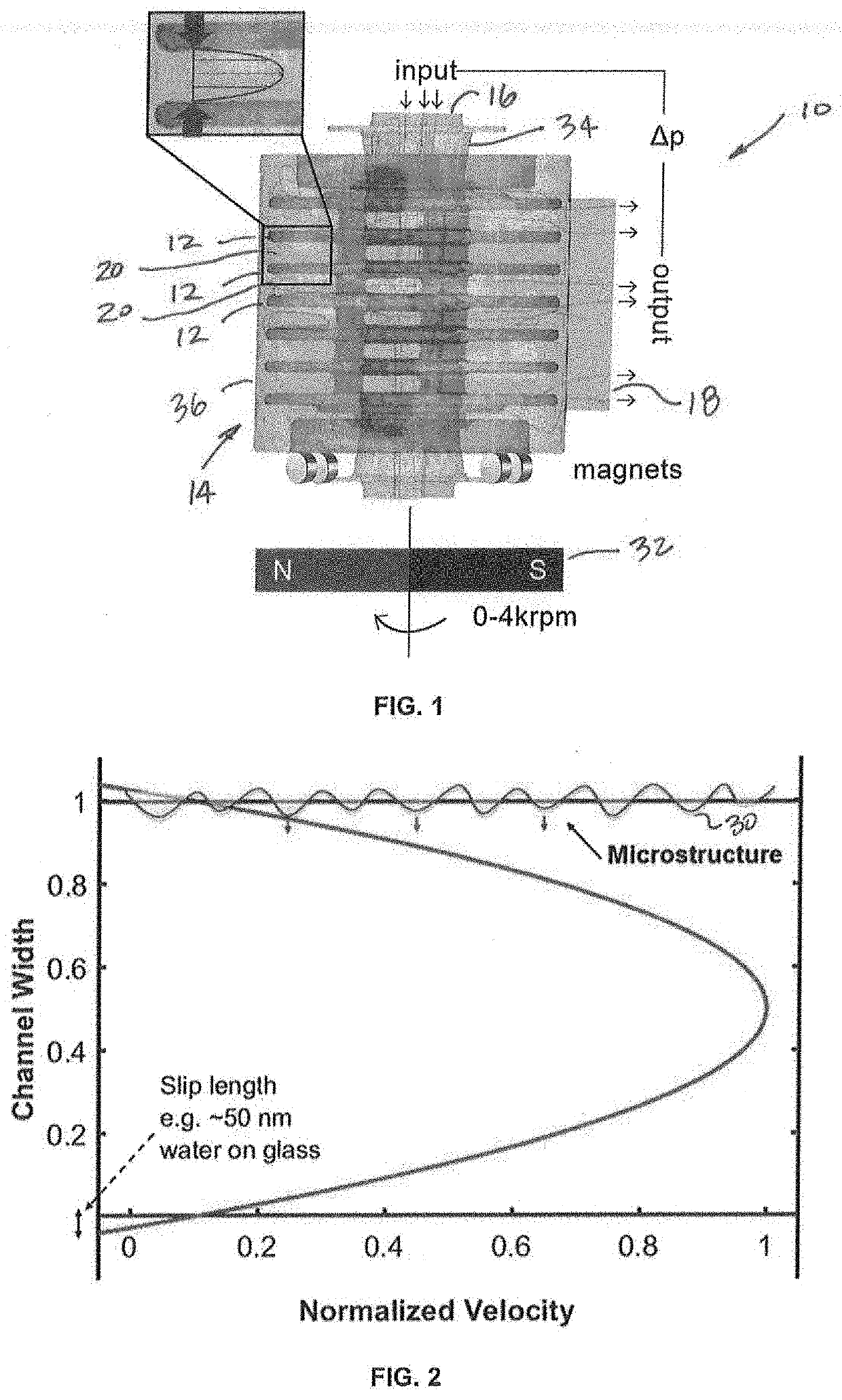
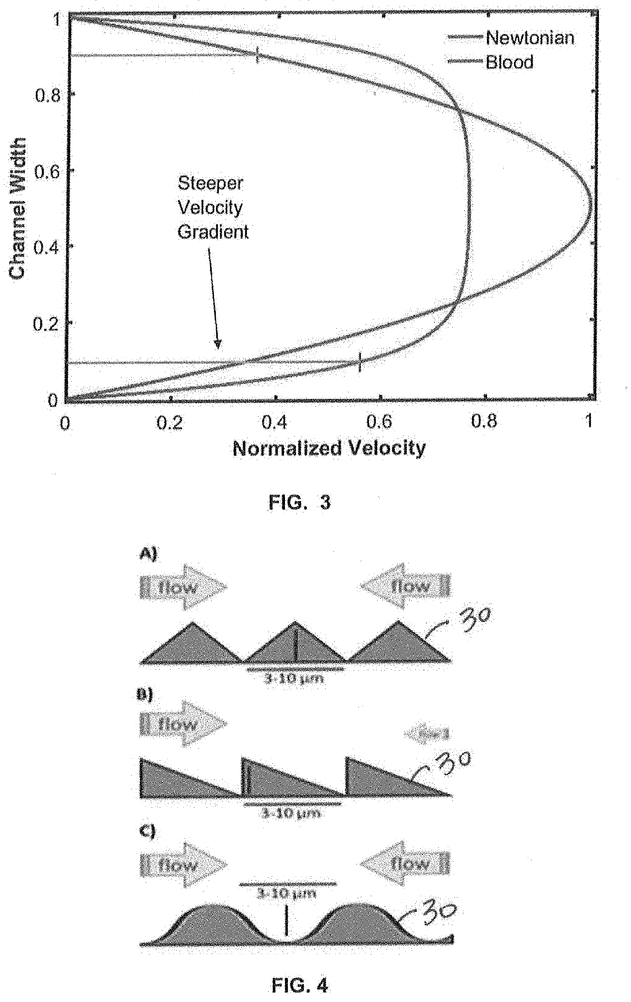
The present patent is about a miniaturized pump that uses low Reynolds number flows to generate pressure without creating fluctuations. This pump has advantages in reducing mechanical damage to blood and hemolysis. The patent also explains how the pump can be used with non-Newtonian fluids and how different optimal points may exist for these fluids. The described surface texture also reduces the slip distance between the fluid and surface. The technical effect of the patent is to provide a pump with improved performance and reduced mechanical damage to blood.

Problems solved by technology

However, these technologies often suffer from a number of disadvantages, as outline in Table 1 below.
However, pumping using these pressure sources incurs shear damage to cellular components in blood, e.g. drops in hematocrit, erythropoietin, and increases in hemolysis due to sharp pressure gradients and time varying flow velocities.
The latter strategy minimizes blood clots from cellular damages, but introduces significant risks of low blood pressure in patients and associated side effects.
However, aforementioned microfluidic pumps cannot provide smooth laminar flow due to their pulsatile driving forces of valves and acoustics, or require applied voltages that render them incompatible with blood flows.

Method used


Image

  • Optimizing pumping of variable viscosities via microtextured miniaturized tesla pump
  • Optimizing pumping of variable viscosities via microtextured miniaturized tesla pump
  • Optimizing pumping of variable viscosities via microtextured miniaturized tesla pump

Examples


Embodiment Construction

[0037]Example embodiments will now be described more fully with reference to the accompanying drawings.

[0038]Example embodiments are provided so that this disclosure will be thorough, and will fully convey the scope to those who are skilled in the art. Numerous specific details are set forth such as examples of specific components, devices, and methods, to provide a thorough understanding of embodiments of the present disclosure. It will be apparent to those skilled in the art that specific details need not be employed, that example embodiments may be embodied in many different forms and that neither should be construed to limit the scope of the disclosure. In some example embodiments, well-known processes, well-known device structures, and well-known technologies are not described in detail.

[0039]The terminology used herein is for the purpose of describing particular example embodiments only and is not intended to be limiting. As used herein, the singular forms “a,”“an,” and “the” ...


PUM


Abstract

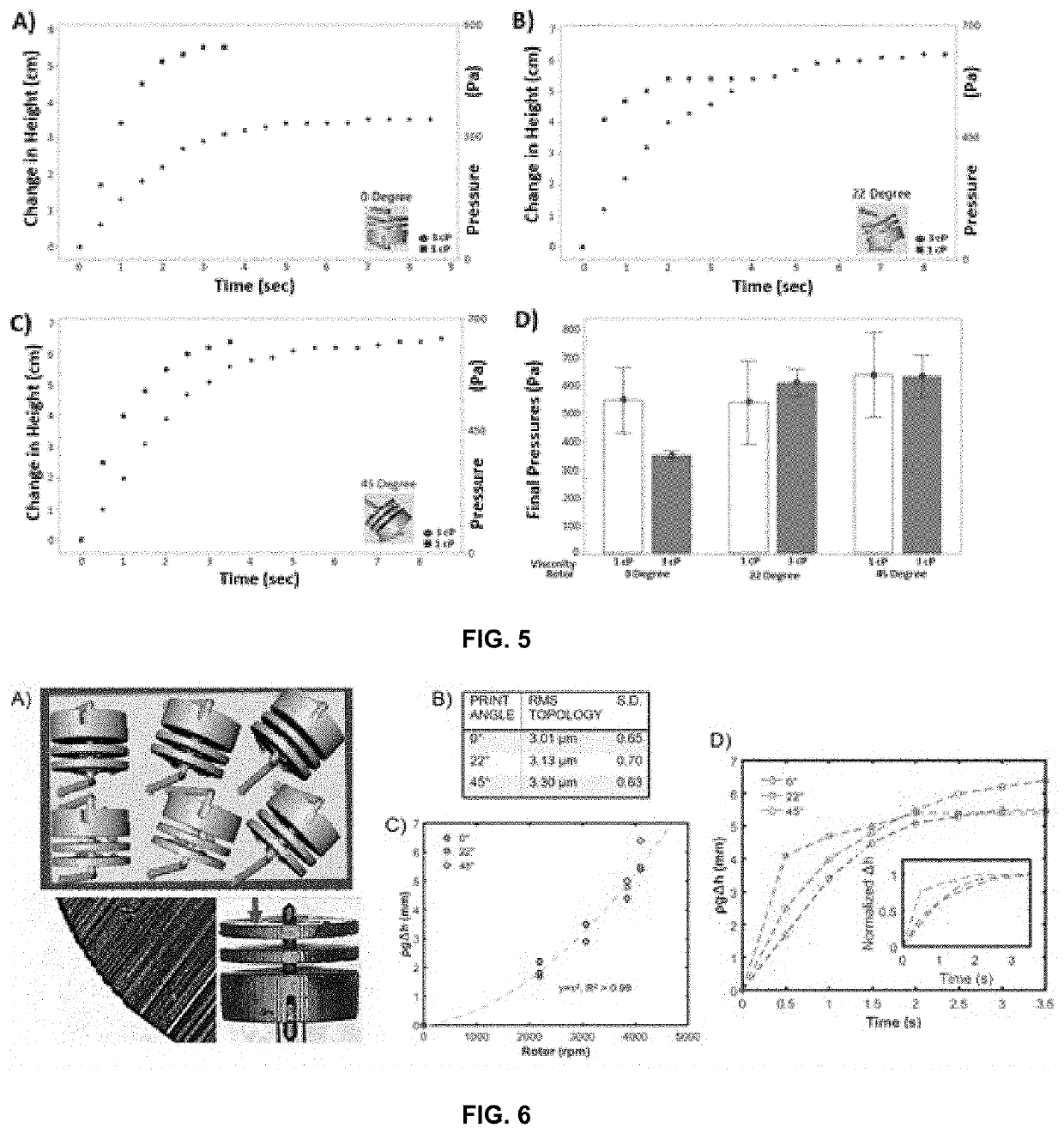
An integrated flow source is a limiting factor in numerous microfluidic applications. In addition to precise gradients and controlling molecular transports, a built-in source of stable and accurate flow can enable novel shear stress modulations for long-term cell culturing studies. The Tesla turbine, when used as a pump on the microfluidic regime, produces stable and accurate fluid gradients by utilizing laminar flow between its rotating discs Utilizing a stereolithography based 3D printer, a tesla pump (Ø10 cm) and associated housing capable of driving a microfluidic gradient is provided having a printed rotor surface topology of the pump in order to enhance pumping of biological fluids like blood at elevated viscosities. The surface topology is tuned via 3D pixilation, and this modulation completely recovered the pressure loss between pumping water at 1 cP versus glycerol solution at 3 cP. As a result, increased fluid viscosities, and even Non-Newtonian viscosities, can be used.

Description

CROSS-REFERENCE TO RELATED APPLICATIONS[0001]This application claims the benefit of U.S. Provisional Application No. 62 / 745,639, filed on Oct. 15, 2018. The entire disclosure of the above application is incorporated herein by reference.FIELD[0002]The present disclosure relates to tesla pumps and, more particularly, relates to methods and systems for optimizing microfluidic pumping of variable viscosities using a miniaturized tesla pump (μ Tesla).BACKGROUND AND SUMMARY[0003]This section provides background information related to the present disclosure which is not necessarily prior art. This section also provides a general summary of the disclosure, and is not a comprehensive disclosure of its full scope or all of its features.[0004]Pumping of biological fluids has remained relatively unchanged in the second half of the 20th century. Pumping is central in a wide range of biomedical applications, including intravenous (IV) infusions, blood transfusions, biofiltration, and hemodialysis...

Claims


Application Information

Patent Timeline
Patent Type & Authority Applications(United States)
IPC IPC(8): F04D7/04F04D1/00F04D13/02F04D29/22F04D29/42A61M60/113A61M60/216A61M60/37A61M60/419
CPCF04D7/04F04D1/00F04D29/426F04D29/22F04D13/024F01D1/34F01D1/36F04D5/001F04D29/688F05D2210/34A61M60/205A61M60/226A61M60/806A61M2205/0238A61M60/109A61M60/37A61M60/39A61M60/10A61M60/113A61M60/419A61M60/216
Inventor LO, JOE FU-JIOU
Owner RGT UNIV OF MICHIGAN
Learn More