Display device

a display device and display technology, applied in the field of display devices, can solve the problems of thinning and full screen of display devices such as mobile phones, and achieve the effect of increasing the screen-to-body ratio and reducing the overall thickness of the display devi

Active Publication Date: 2021-11-25
BEIJING BOE OPTOELECTRONCIS TECH CO LTD +1
View PDF0 Cites 0 Cited by
  • Summary
  • Abstract
  • Description
  • Claims
  • Application Information

AI Technical Summary

Benefits of technology

[0005]Embodiments of the present disclosure provide an improved camera module configuration, which effectively utilizes the Z-direction space in the display module structure, thus reducing the overall thickness of the display device and substantially increasing the screen-to-body ratio.

Problems solved by technology

Because of the existence of the flexible printed circuit board, the (mobile phone) middle case and the bracket, the camera module, as an independent unit, has greatly hindered the trend of thinning and full screen of display devices such as mobile phones.

Method used


Image

  • Display device
  • Display device
  • Display device

Examples


first embodiment

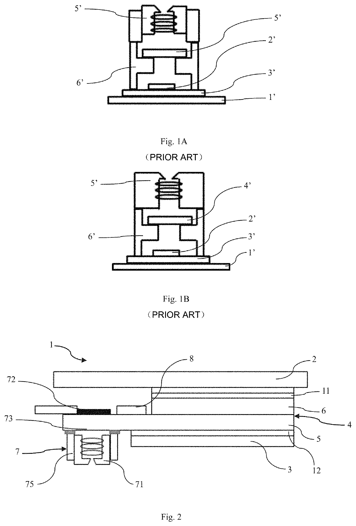
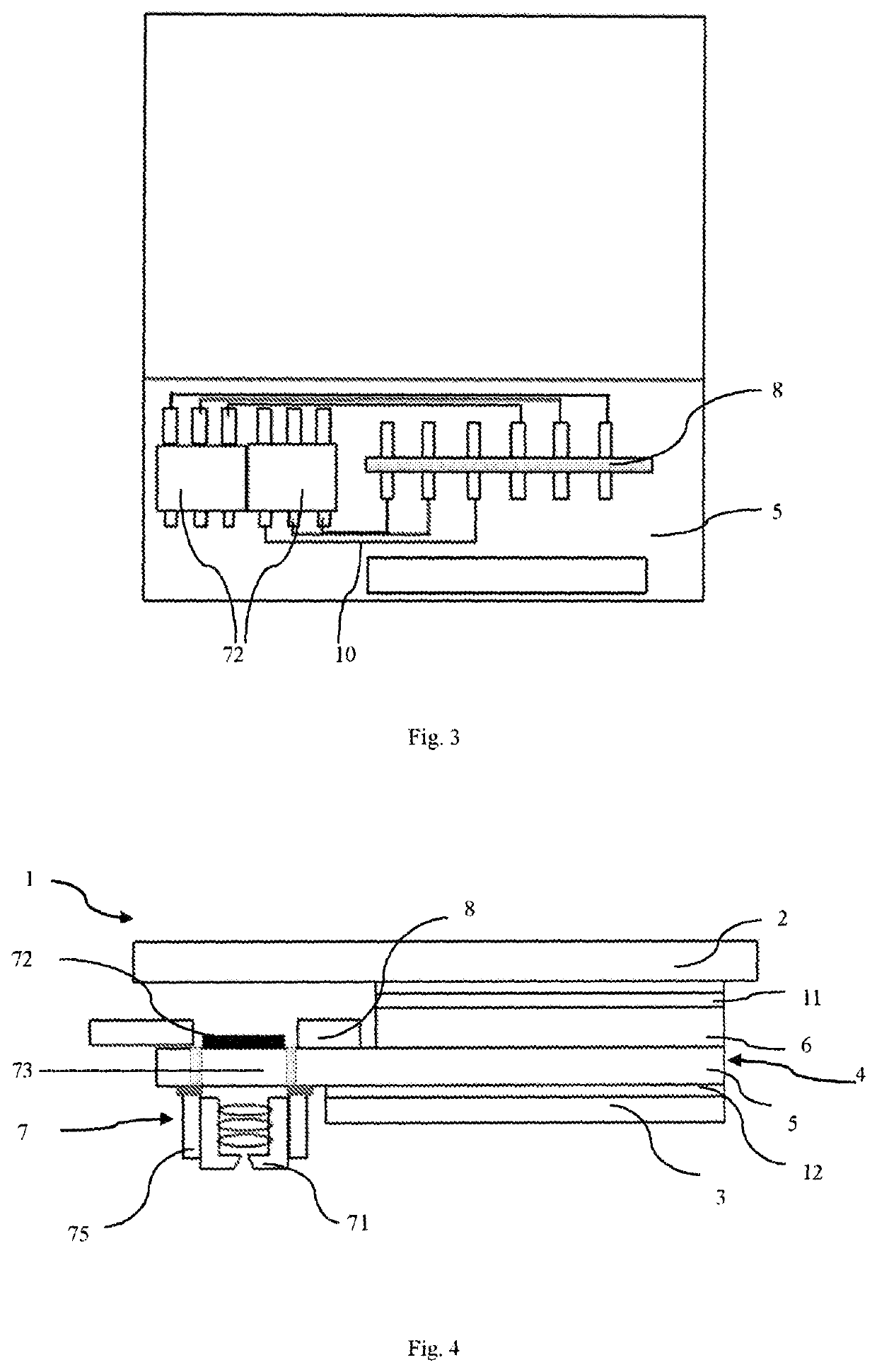
[0030]FIG. 2 shows a schematic structural view of a display device according to the present disclosure. As can be seen from the figure, the display device 1 includes a cover plate 2, a backlight unit 3, and a display module 4 disposed between the cover plate 2 and the backlight unit 3, wherein the display module 4 includes a first substrate 5 close to the light emitting side of the backlight unit and a second substrate 6 close to the cover plate, and the first substrate 5 has a first side facing the second substrate 6 and a second side facing the backlight unit 3. The display device 1 further includes a camera module 7 disposed on the first substrate 5, the camera module includes a lens 71 for collecting light, a sensor 72 capable of receiving light from the lens and forming sensing information, and a voice coil motor 75 for driving the lens 71. The display device 1 further includes an upper polarizer 11 disposed between the cover plate 2 and the second substrate 6 and a lower polar...

third embodiment

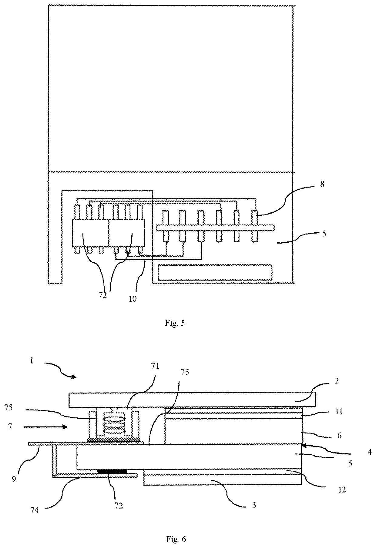
[0038]In this third embodiment, the display module includes a main flexible printed circuit board 9 disposed between the lens 71 and the first substrate 5, and the camera module 7 further includes a sensor flexible printed circuit board 74 for the sensor 72, wherein the main flexible printed circuit board 9 is electrically connected to the sensor flexible printed circuit board 74 through, for example, an indium tin oxide trace to drive the sensor.

[0039]In this embodiment, an infrared cut-off filtering film is used to replace the infrared cut-off filtering sheet in the existing camera module, and the display module 4 and the sensor 72 of the camera module 7 share the main flexible printed circuit board, so that the flexible printed circuit board dedicated to the sensor for wiring connection in the traditional camera module is eliminated, thereby reducing the thickness of the camera module and the display module, and further reducing the thickness of the display device.

[0040]FIG. 7 sh...


PUM

PropertyMeasurementUnit
flexibleaaaaaaaaaa
thicknessaaaaaaaaaa
areaaaaaaaaaaa

Abstract

The disclosure relates to a display device, which includes a cover plate, a backlight unit, a display module disposed between the backlight unit and the cover plate, the display module including a first substrate close to the light exiting side of the backlight unit and a second substrate close to the cover plate, and a camera module arranged on the first substrate, the camera module including an infrared cut-off filter, wherein the first substrate extends horizontally beyond the second substrate and the backlight unit to form a mounting section for the camera module, and the infrared cut-off filter is arranged in the mounting section.

Description

CROSS REFERENCE TO RELATED APPLICATIONS[0001]This patent application is a National Stage Entry of PCT / CN2019 / 085153 filed on Apr. 30, 2019, the disclosure of which is incorporated by reference herein in its entirety as part of the present application.BACKGROUND[0002]The present disclosure relates generally to the field of display technology, in particular to a display device with reduced thickness and effectively increased screen-to-body ratio.[0003]With the continuous development of electronic information technology, display devices, such as smart phones and tablet computers, are widely used and play an indispensable role in people's work and life.[0004]With the increasing popularity of display devices, ultra-narrow bezel, thinning and full screen of the display devices have become the mainstream trend. As the traditional camera exists as an independent unit in the device, it occupies a large space, which is not conducive to ultra-thinning and full screen. FIGS. 1A and 1B show conv...

Claims


Application Information

Patent Timeline
Patent Type & Authority Applications(United States)
IPC IPC(8): H01L25/18H01L27/12H04N5/225
CPCH01L25/18H01L27/124H01L27/1218H04N5/2254H04N5/2253H04N5/2257G02F1/1333G02B7/04H04N23/57H04N23/55H04N23/54H10K59/00
Inventor LI, ZHONGHUAWANG, SHIPENGSANG, JIANGUO, SHAOFEIHAO, DONGJIAQIAO, CHUNYING
Owner BEIJING BOE OPTOELECTRONCIS TECH CO LTD
Why Eureka
Try Eureka