Electrical spool device having increased electrical stability

a technology of electrical stability and spool, which is applied in the direction of superconductors/hyperconductors, superconducting magnets/coils, magnetic bodies, etc., can solve the problems of limited current density of such a spool, difficult to use impregnating resin or potting compound to create a well-defined distance between the conducting areas of individual turns, and short charging. , the effect of high time constan

Pending Publication Date: 2021-12-02
ROLLS ROYCE DEUT LTD & CO KG
View PDF0 Cites 0 Cited by
  • Summary
  • Abstract
  • Description
  • Claims
  • Application Information

AI Technical Summary

Benefits of technology

The spool device has several advantages, including effective protection against quenching damage. The mechanism for this protection is the electrical cross connection between adjacent turns. If the current flowing in the spool winding is below the critical current, the current flows almost loss-free via the spiral main electrical path. If the critical current is exceeded, a small portion of the current may flow directly from turn to turn via the additional cross connections created by the coupling layer. This transfer of current happens with a high material cross section available in the coupling layer, so the risk of localized heating and damage is significantly reduced. The spool device also has a comparatively high time constant for electrical charging and discharging, which allows for longer charging and discharging times without overheating. The coupling layer provides a thin, accurately adjustable electrical coupling from turn to turn with homogeneous deposition. A moderate electrical coupling of the adjacent turns is particularly advantageous to achieve an adequate effect of protection during quenching without excessive charging and discharging times.

Problems solved by technology

Such a well-defined distance between the conductor turns only be achieved by other methods with relative difficulty.
In both cases, however, it is difficult to use the impregnating resin or the potting compound to create a well-defined distance between the conducting areas of the individual turns.
A disadvantage of the known spool windings is that the current density of such a spool is limited, even with very high current carrying capacities of the superconducting layer, by the possibly quite high layer thicknesses of the substrate, the insulating layer, and the optionally present metallic cover layers.
However, the disadvantage of such rapidly charging and discharging spool windings is that the spool windings may also quench very easily and may be damaged by such a quench if the critical current of the spool winding is reached or exceeded in the event of a fault.
This sudden introduction of heat leads to a loss of the superconducting properties and may lead to strong local heating and, as a result, to thermal damage to the superconductor material.
If there is bath cooling, (e.g., if the superconducting spool winding is bathed in a liquid cryogenic coolant), there may also be an undesirable sudden evaporation of parts of the liquid coolant.

Method used


Image

  • Electrical spool device having increased electrical stability
  • Electrical spool device having increased electrical stability
  • Electrical spool device having increased electrical stability

Examples


Embodiment Construction

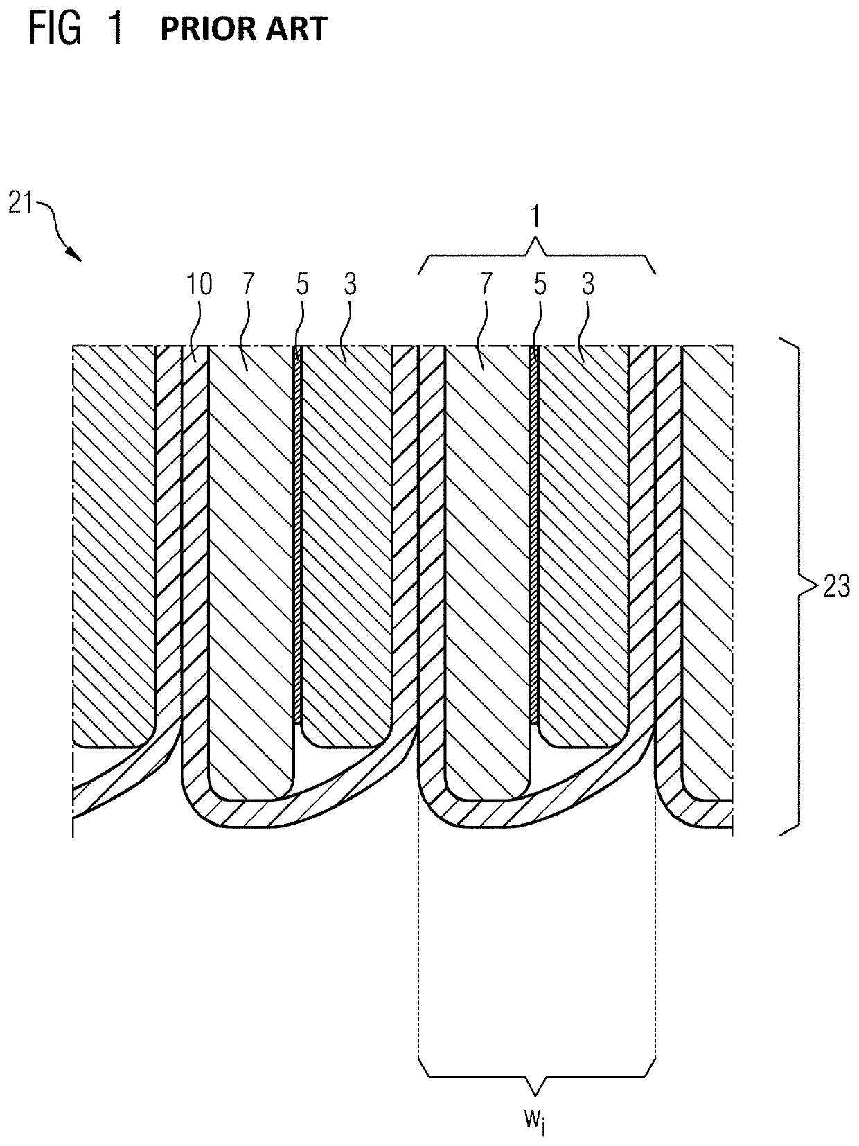
[0041]FIG. 1 depicts a detail from a spool device 21 with a spool winding 23 according to the prior art. A partial region of a cross section of the spool winding 23 in an edge region of the winding is shown. The spool winding 23 here includes a multiplicity of turns wi, of which, by way of example, only the edge regions of two turns are shown in full and the edge areas of the two adjoining turns are partially shown. The individual turns wi are formed by winding a strip conductor 1, the structure of which will now be explained in more detail. The strip conductor 1 has a metallic substrate 3, on one main surface of which a two-dimensional superconducting layer 5 is formed. This superconducting layer 5 is covered by a normally conducting cover layer 7, which may likewise be formed from a metallic material, (e.g., copper and / or silver). Each of the layers shown may include a number of partial layers and additional intermediate layers may also be arranged between the individual layers, i...


PUM

PropertyMeasurementUnit
time constantaaaaaaaaaa

Abstract

An electrical spool device having at least one coil winding composed of a superconducting strip conductor is specified. The strip conductor includes: a strip-type substrate having two main surfaces; at least one planar superconducting layer applied on a first main surface of the substrate; and at least one outer electrical coupling layer applied on at least one of the main surfaces of the conductor composite thus formed. In this case, the coupling layer brings about an electrical coupling of adjacent turns of the coil winding, wherein the electrical coupling is dimensioned such that the time constant for electrical charging and / or discharging of the coil winding is in the range of 0.02 seconds and 2 hours.

Description

[0001]The present patent document is a § 371 nationalization of PCT Application Serial No. PCT / EP2019 / 075647, filed Sep. 24, 2019, designating the United States, which is hereby incorporated by reference, and this patent document also claims the benefit of German Patent Application No. 10 2018 216 904.7, filed Oct. 2, 2018, which is also hereby incorporated by reference.TECHNICAL FIELD[0002]The present disclosure relates to an electrical spool device with at least one spool winding of a superconducting strip conductor, wherein the strip conductor includes a strip-shaped substrate with two main surfaces and at least one two-dimensional superconducting layer applied to a first main surface of the substrate.BACKGROUND[0003]Numerous electrical spool devices with spool windings of superconducting strip conductors are known from the prior art. For example, such spool windings are used as excitation spools in rotating machines, as storage spools in superconducting magnetic energy storage d...

Claims


Application Information

Patent Timeline
Patent Type & Authority Applications(United States)
IPC IPC(8): H01B12/06H01B12/14H01F6/02H01F6/06
CPCH01B12/06H01F6/06H01F6/02H01B12/14Y02E40/60
Inventor FILIPENKO, MYKHAYLOFRANK, MICHAELGRUNDMANN, JÖRNVAN HASSELT, PETER
Owner ROLLS ROYCE DEUT LTD & CO KG
Why Eureka
Try Eureka