Portable soil mass in-situ shear test device and test method thereof

a soil mass and test device technology, applied in the field of soil mass insitu shear test, can solve the problems of large dispersion of soil shear strength index, poor representation, and general time-consuming indoor soil shear test methods, and achieve the effects of simple structure, convenient portability and maintenance, and simple structur

Active Publication Date: 2021-12-23
SOUTHWEST JIAOTONG UNIV
View PDF3 Cites 7 Cited by
  • Summary
  • Abstract
  • Description
  • Claims
  • Application Information

AI Technical Summary

Benefits of technology

[0031]1. The present invention has a simple structure and is easy to carry and maintain. As an in-situ test equipment, the device has a simple structure and small size, which is easy to carry and requires no sensing device or fixed power supply. The device is more suitable for field tests.
[0032]2. The applicability is strong. The present invention is suitable not only for layered soil with large cross-plate shear test error, but also for various sites and various terrains, which can perform soil mass shear strength in-situ test on flat ground as well as on slope surface.
[0033]3. Pressure supply is stability. Compared with the normal stress provided by motor servo and man-made mechanical force, the normal stress of the present invention is provided electromagnet. The stable pressure supply ensures the reliability test data.
[0034]4. The test period is significantly shortened and the efficiency is improved. Generally, the indoor triaxial shear test requires at least one week, but the method of the present invention is less than one hour for one set of tests, which significantly shortens the test period.

Problems solved by technology

However, due to the size limitation of the samples in indoor test, the representativeness is poor.
In addition, artificiality of the empirical criterion will lead to a large dispersion of the soil shear strength index.
More importantly, the indoor soil shear test method generally takes a long time.
Firstly, the shear test sample changes the environmental conditions of the tested soil mass.
Secondly, the surface soil is so loose that it is often impossible to get the shear test sample.
Therefore, the test is usually unable to perform.
However, the conventional large-scale direct shear test has disadvantages such as high costs, long periods, and complicated operations.
First, the conventional large-scale in-situ tests often has the disadvantages such as high costs, long periods, and complicated operations, resulting in a small scope of application. They are often used for large-scale important projects since such tests cannot be performed anytime and anywhere.
Second, when the conventional cross-plate shear test is carried out, since there is a time difference between the side and top surfaces of a cylinder to reach shear failure, the strength obtained is not the true peak value, but an average shear strength. Therefore, it cannot truly reflect the true shear strength of the soil mass.
Third, the conventional cross-plate shear test adopts three shear surfaces, namely an upper shear surface, a side shear surface, and a lower shear surface, and the spatial correlation of the three shear surfaces is relatively small. Therefore, there are large errors in the shear strength test of layered soil mass.
Fourth, the conventional in-situ soil mass shear strength test can only measure the shear strength of the soil mass under a natural stress state, and cannot simulate the shear strength and changes of the soil mass when an overburden load exists, and thus causing certain limitations.

Method used


Image

  • Portable soil mass in-situ shear test device and test method thereof
  • Portable soil mass in-situ shear test device and test method thereof
  • Portable soil mass in-situ shear test device and test method thereof

Examples


Embodiment Construction

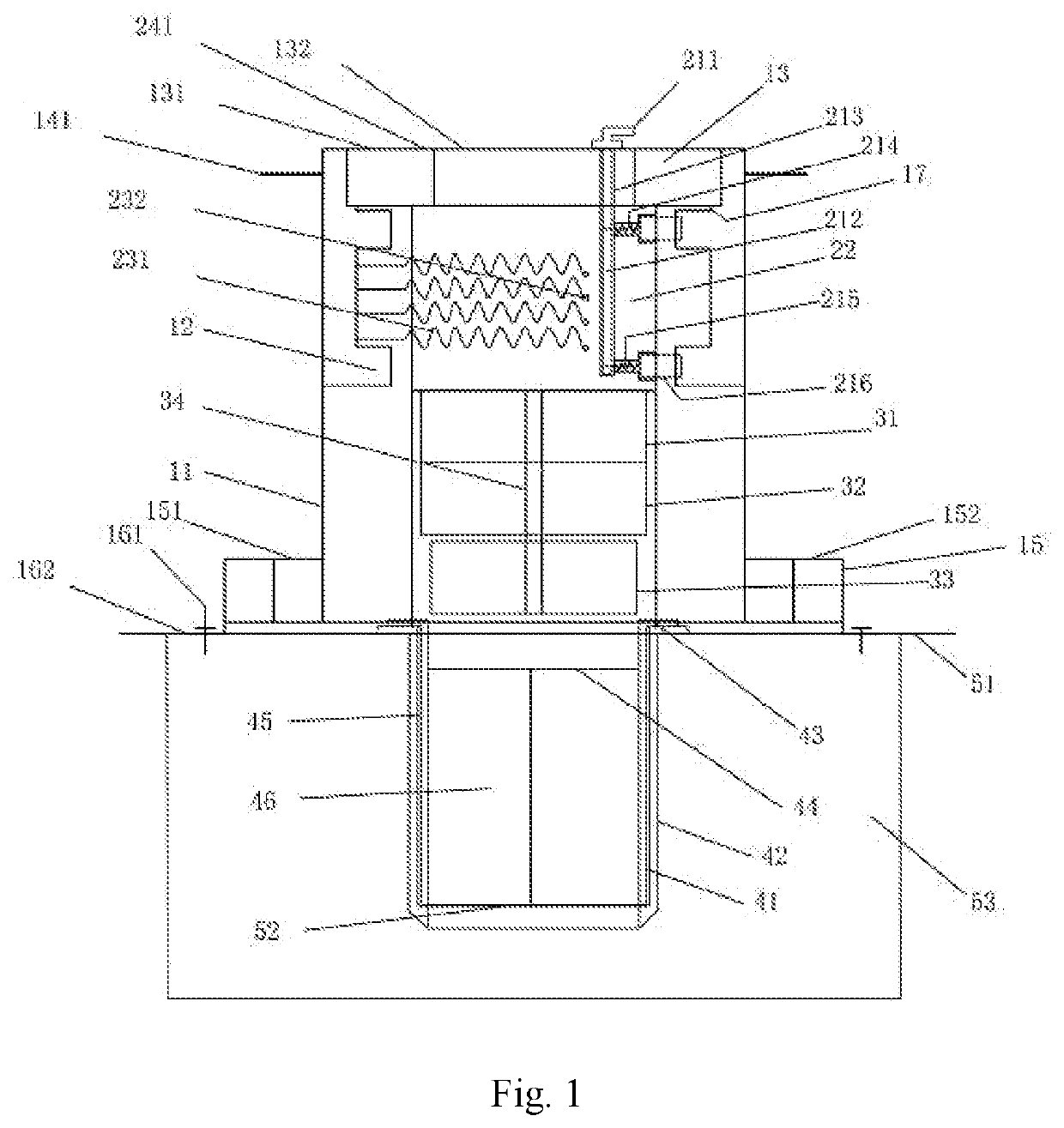
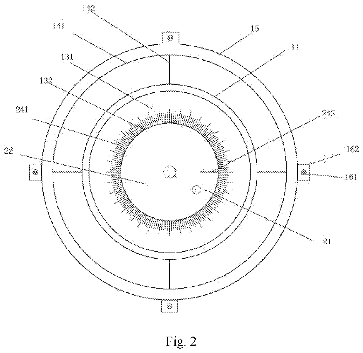
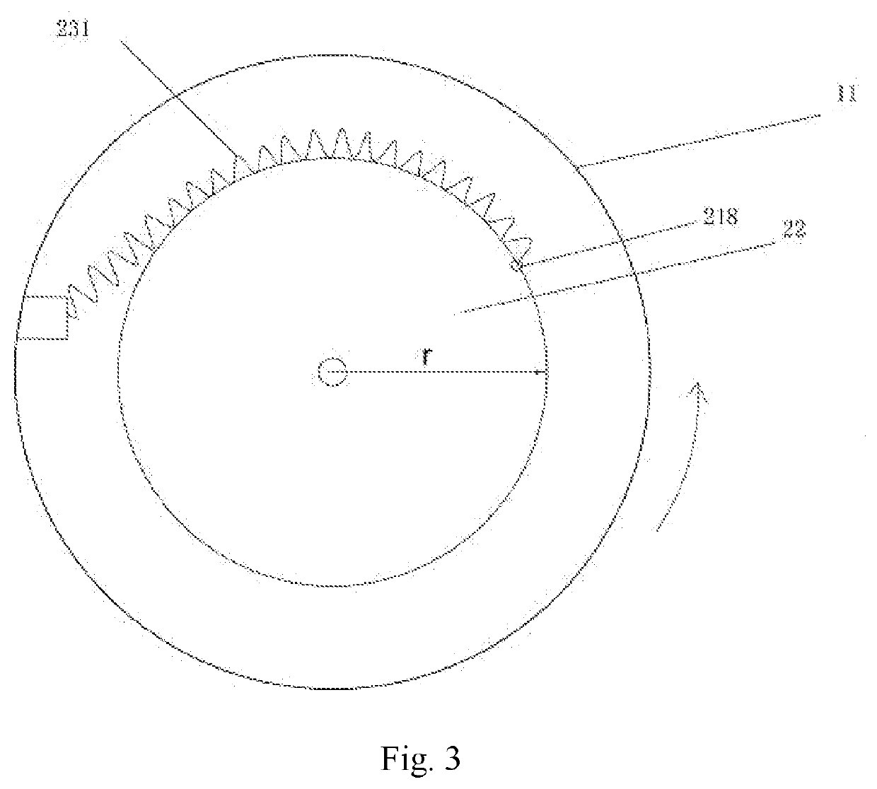
[0042]Referring to the drawings, embodiments of the present invention will be further described. Element references are: 11—casing, 12—ratchet groove, 13—upper bearing, 131—upper bearing outer ring, 132—upper bearing inner ring, 141—force turntable, 142—connecting rod (of the force turntable), 15—lower bearing, 151—lower bearing inner ring, 152—lower bearing outer ring (having a top horizontal edge), 161—anchor, 162—anchoring counter—pressure plate, 17—upper bearing holder, 211—ratchet tooth reset knob, 212—ratchet tooth reset (knob) rod, 213—internal hole (of the shear core) (referring to FIG. 2, the internal hole is located at an eccentric position of the shear core), 214—ratchet tooth spring, 215—ratchet tooth pull rope, 216—ratchet tooth, 217—ratchet tooth reset groove, 218—ratchet tooth hinge joint, 219—cylinder groove, 22—shear core (comprising an upper cylinder with a smaller diameter, a middle cylinder with a larger diameter, a lower cylinder whose inner diameter is the same...


PUM

PropertyMeasurementUnit
massaaaaaaaaaa
shear strength testaaaaaaaaaa
pressureaaaaaaaaaa

Abstract

A portable soil body in-situ shear test device includes four parts: an active force system forming arranged externally, a passive shear system and an electromagnetic loading system forming arranged internally, and a ring knife system arranged at a bottom. Compared with the conventional in-situ soil shear strength test device and test method, the present invention is convenient to install and carry as well as simple to operate, and has strong applicability. The present invention is suitable not only for layered soils with large cross-plate shear test errors, but also for soils with different consolidation degrees at various sites and various terrains. A test method adopting the device can simulate the shear strength of the soil mass under different overburden loads without disturbing the mechanical properties of the in-situ soil mass, which has high promotion value in the test of in-situ soil shear strength.

Description

CROSS REFERENCE OF RELATED APPLICATION[0001]The present invention claims priority under 35 U.S.C. 119(a-d) to CN 202110051470.0, filed Jan. 15, 2021.BACKGROUND OF THE PRESENT INVENTIONField of Invention[0002]The present invention relates to a technical field of soil mass in-situ shear test, and more particularly to a portable soil mass in-situ shear test device and a test method thereof.Description of Related Arts[0003]The shear strength of soil refers to the ultimate strength of soil mass against shear failure, including cohesion (c) and internal friction angle (1), which is an important mechanical property of soil, and is also an important parameter to calculate slope stability of road cuts, channels, embankments, and earth dams, as well as to calculate soil pressure for supporting buildings. The in-situ test can determine the engineering mechanical properties of the soil mass at the original position thereof with basically maintained natural structure, natural water content and n...

Claims


Application Information

Patent Timeline
Patent Type & Authority Applications(United States)
IPC IPC(8): G01N3/24G01N33/24
CPCG01N3/24G01N33/24G01N2203/0266G01N2203/005G01N2203/0246G01N2203/0025G01N2203/0003G01N2203/0256G01N2203/0605G01N2203/0284
Inventor JIN, TAOHU, XIEWENZHAO, LIMINGHUANG, GUANGLINZHENG, RUIJIEHE, XURONGXUE, SONGHAN, MEIXI, CHUANJIEYANG, XIANGBIN
Owner SOUTHWEST JIAOTONG UNIV
Why Eureka
Try Eureka