Top chamber cavities for center-pinned actuators

Pending Publication Date: 2021-12-30
FRORE SYST INC
View PDF5 Cites 0 Cited by
  • Summary
  • Abstract
  • Description
  • Claims
  • Application Information

AI Technical Summary

Problems solved by technology

However, such active and passive devices may be unable to adequately cool both mobile

Method used


Image

  • Top chamber cavities for center-pinned actuators
  • Top chamber cavities for center-pinned actuators
  • Top chamber cavities for center-pinned actuators

Examples


Example

[0016]The invention can be implemented in numerous ways, including as a process; an apparatus; a system; a composition of matter; a computer program product embodied on a computer readable storage medium; and / or a processor, such as a processor configured to execute instructions stored on and / or provided by a memory coupled to the processor. In this specification, these implementations, or any other form that the invention may take, may be referred to as techniques. In general, the order of the steps of disclosed processes may be altered within the scope of the invention. Unless stated otherwise, a component such as a processor or a memory described as being configured to perform a task may be implemented as a general component that is temporarily configured to perform the task at a given time or a specific component that is manufactured to perform the task. As used herein, the term ‘processor’ refers to one or more devices, circuits, and / or processing cores configured to process da...


PUM


Abstract

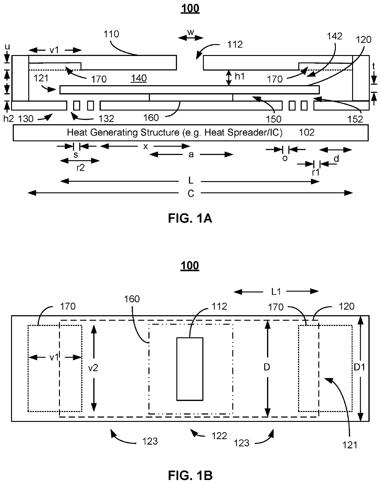
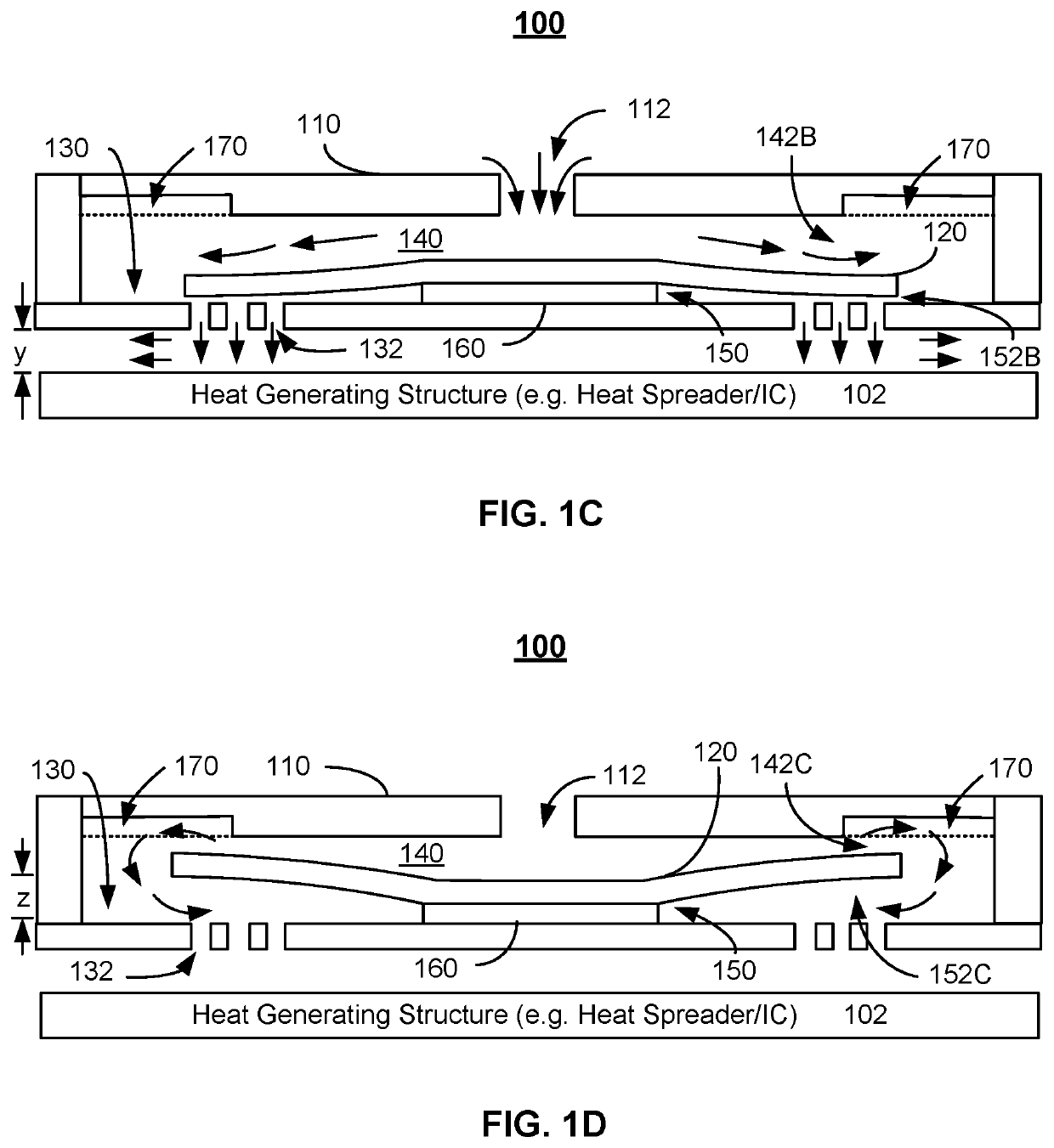
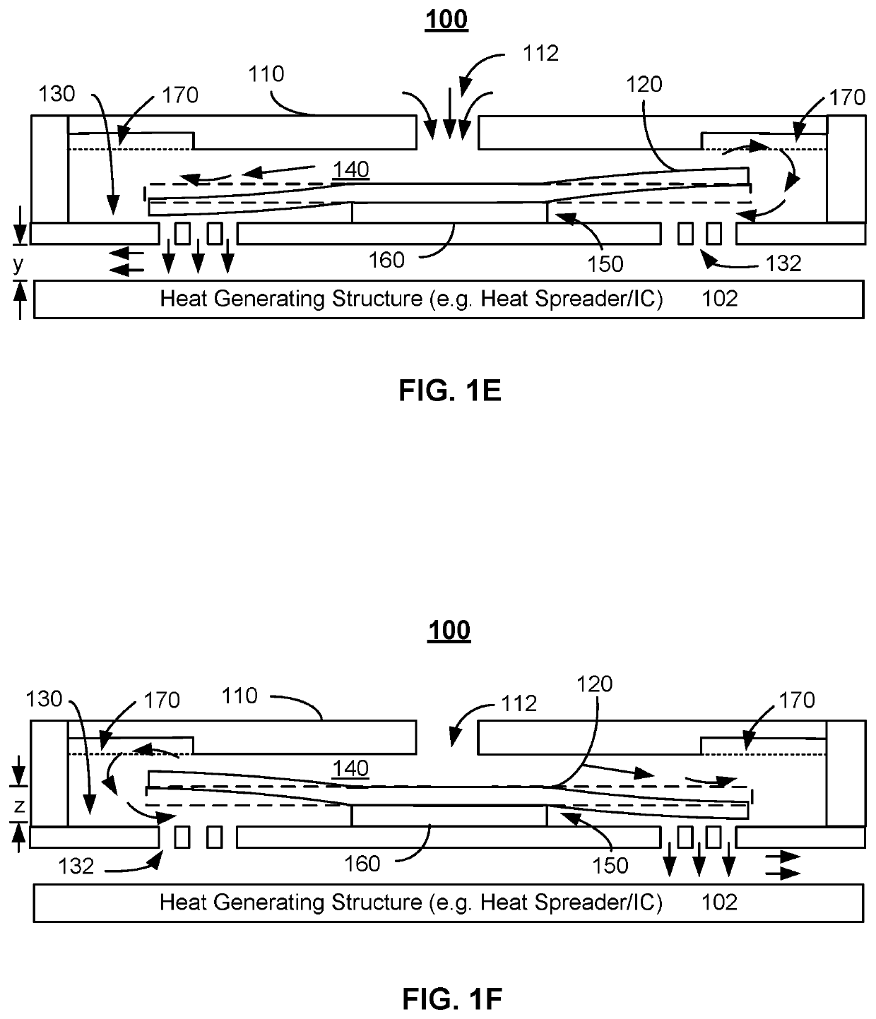
A flow chamber, a cooling system and a method are described. The flow chamber includes an upper chamber including a top wall, an actuator, and a lower chamber. The actuator is located distally from the top wall. The lower chamber receives fluid from the upper chamber when the actuator is actuated. The top wall includes at least one cavity therein. The cooling system utilizes cooling cells including the flow chamber. The method includes driving the actuator at a frequency that directs fluid through the flow chamber.

Description

CROSS REFERENCE TO OTHER APPLICATIONS[0001]This application is a continuation in part of U.S. patent application Ser. No. 16 / 915,912 entitled CENTRALLY ANCHORED MEMS-BASED ACTIVE COOLING SYSTEMS filed Jun. 29, 2020, which claims priority to U.S. Provisional Patent Application No. 62 / 945,001 entitled CENTRALLY ANCHORED MEMS-BASED ACTIVE COOLING SYSTEMS filed Dec. 6, 2019, both of which are incorporated herein by reference for all purposes.BACKGROUND OF THE INVENTION[0002]As computing devices grow in speed and computing power, the heat generated by the computing devices also increases. Various mechanisms have been proposed to address the generation of heat. Active devices, such as fans, may be used to drive air through large computing devices, such as laptop computers or desktop computers. Passive cooling devices, such as heat spreaders, may be used in smaller, mobile computing devices, such as smartphones, virtual reality devices and tablet computers. However, such active and passive...

Claims


Application Information

Patent Timeline
IPC IPC(8): F28F13/10
CPCF28F13/10F28D2021/0028H01L23/467G06F1/203G06F2200/201H05K7/2049
Inventor MUKUNDAN, VIKRAMGANTI, SURYAPRAKASHYALAMARTHY, ANANTH SARANMADHAVAPEDDY, SESHAGIRI RAOSATHYAMURTHY, PRABHURAYAPATI, NARAYANA PRASAD
Owner FRORE SYST INC
Why Eureka
Try Eureka