A lower pair arc stop-block overrunning clutch

a technology of stop-block and stop-block, which is applied in the field of clutches, can solve the problems of significant reduction of torque withstand performance of the over-running clutch, wedging performance, and the working life of the wedge, and achieves the effects of improving wear resistance performance, reducing torque, and reducing torqu

Active Publication Date: 2022-01-06
XINING KEJIN INDUSTRIAL DESIGN CO LTD
View PDF0 Cites 3 Cited by
  • Summary
  • Abstract
  • Description
  • Claims
  • Application Information

AI Technical Summary

Benefits of technology

[0051]The present invention provides a friction block assembly, a first propeller assembly and a synchronized push-block assembly between the inner and outer rotating elements, wherein the friction block assembly is composed of a plurality of friction blocks connected end to end to form an annular structure, which achieves synchronous rotation of the plurality of friction blocks in the friction block assembly by driving the first propeller assembly to move through the drive element in the inner and outer rotating elements and the first propeller assembly pushing the synchronized push-block assembly; the first propeller assembly strikes the friction block assembly and is relatively stationary to push the friction block assembly for generating reverse rotation relative to the driven element so that the wedge assembly is wedged to generate a radial pressure on the friction block assembly, then the cambered-surface stop surface of the friction block assembly holds tightly the drive element and the friction block assembly achieves lower-pair cambered-surface stop with the drive element and locks with the driven element by wedging, respectively, thus truly achieving lower-pair stop through the cooperation between the friction block assembly and the cambered-surface of rotating elements, improving maximally the capacity of withstanding torque for the overrunning clutch, being able to be applied in a variety of working occasions of high-speed, large torque and strong impact. Compared with prior art, the overrunning clutch of the present invention has a more sensitive reaction, better wear resistance performance, ultra-long service life, and serious heat phenomenon will not occur even after a long-time, high-intensity operation.

Problems solved by technology

As the only level adjustment for clutch stroke in the ratchet overrunning clutch and the noise and impact wear easily caused by the pawl sliding on the tooth back, such clutch is not suitable for high-speed occasions; in the roller overrunning clutch, since the torque and the friction force are mainly transmitted through the rollers, the force transmitting units mainly contact with each other through linear contact, and the area of the stress is often increased by increasing the number of the rollers in the prior art, there nevertheless is a big limitation, i.e. the service life of products in high load situations is still not long; in the wedge overrunning clutch, the selection of wedging angle cannot be balanced with the wear resistance and the torque transmitting performance, and the smaller the wedging angle is, the better the wedging performance is, however, as the wedges reduce the effective friction layer that is used to withstand wear and the wear resistance deteriorates, the working life of the wedges will reduce, in addition, if the wedge angle is increased, the wedging performance is relatively weakened though the effective friction layer is increased and the abrasion resistance is enhanced, thereby leading to a significant reduction of torque withstand performance of the overrunning clutch.
The higher-pair transmission of existing overrunning clutches such as point contact or linear contact cannot capable of withstanding large torques and at the same time serious heating phenomenon resulted from long-time operation is inevitably led by, though, achieving the capacity of increasing torque through increasing contact areas.
Its structural characteristics determine the limitation on application and low service life, making the working reliability and use performance of equipment utilizing overrunning clutch become significantly lower.

Method used


Image

  • A lower pair arc stop-block overrunning clutch
  • A lower pair arc stop-block overrunning clutch
  • A lower pair arc stop-block overrunning clutch

Examples


embodiment 1

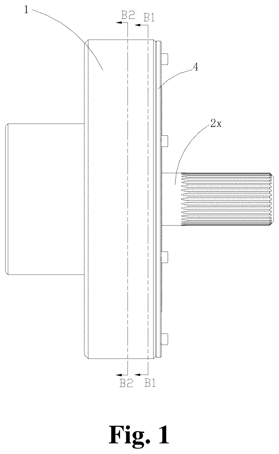
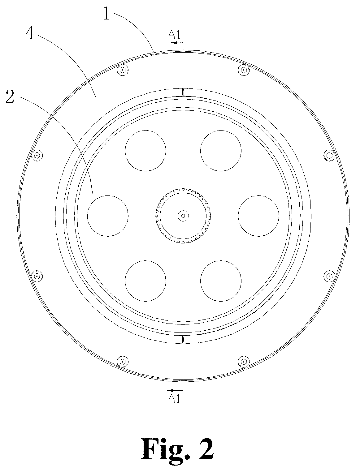
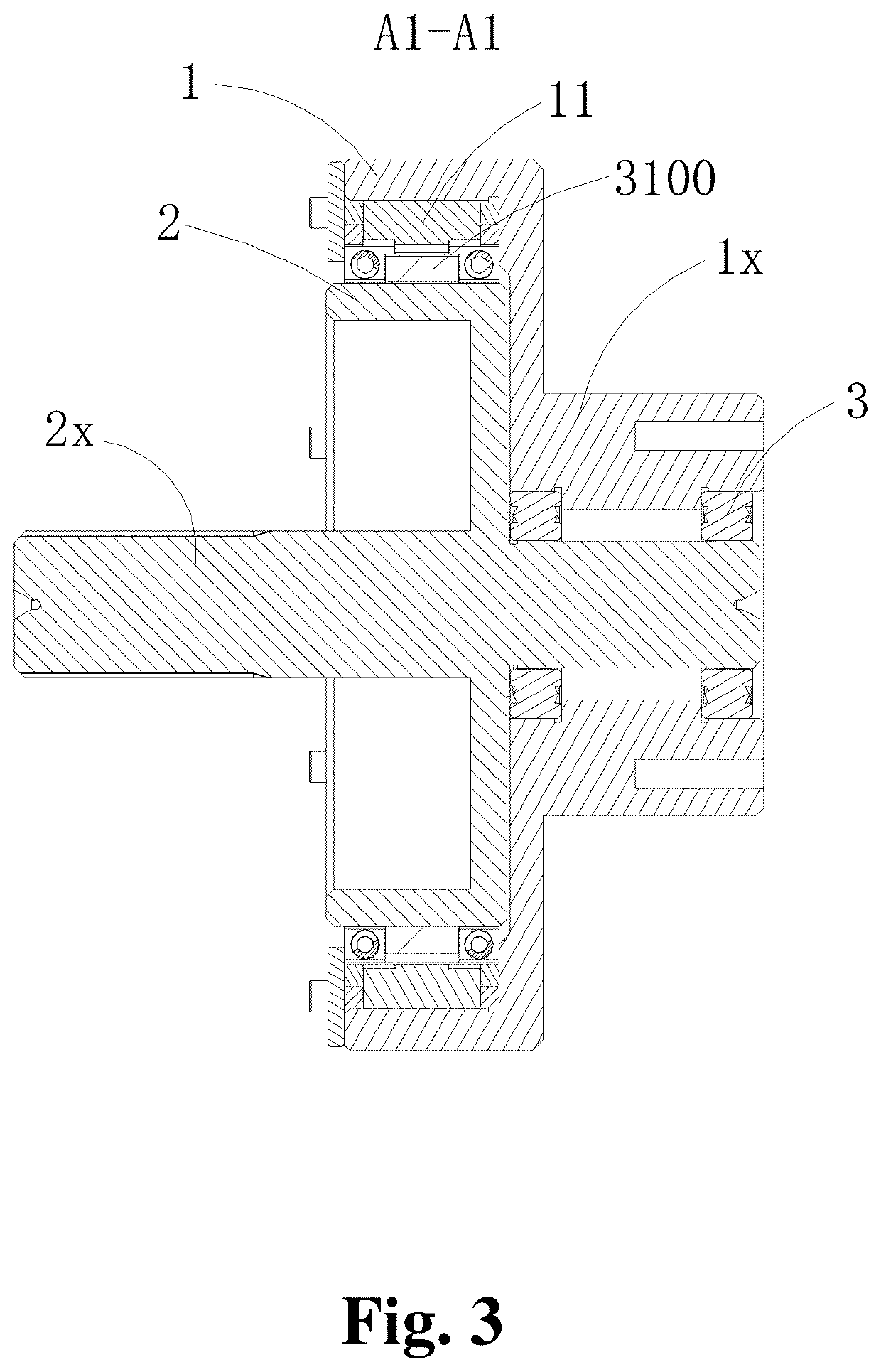
[0072]With reference to FIG. 1-3, the overrunning clutch of the present invention comprises an outer rotating element 1, an inner rotating element 2 and a clutch cover plate 4, wherein the outer rotating element 1 includes a shaft sleeve 1x and the inner rotating element 2 includes a shaft 2x; one end of the shaft 2x is fixed with a bearing 3 and the outer surface of the bearing 3 snaps into the shaft sleeve 1x so that the inner rotating element 2 can rotate more smoothly relative to the outer rotating element 1. When the inner rotating element 2 is mounted to the clutch cover plate 4 on the rear cover in the outer rotating element 1, the axial clearance of the structure in the outer rotating element 1 during rotation can be limited.

[0073]The outer rotating element 1 and inner rotating element 2 can be connected to an external transmission mechanism respectively by the shaft sleeve 1x and shaft 2x for application onto various occasions of toque transmission. When the inner rotating ...

embodiment 2

[0107]As shown in FIG. 12, different from Embodiment 1, the first lapping part and second lapping part at the end surfaces of the head and tail of each friction block are another structures different from Embodiment 1, specifically, both the first lapping part and second lapping part are configured to be an anti-hook structure extending from the end surfaces of friction blocks and folding outward while forming a first insert hole 100a at the first lapping part and a notch 100c at the second lapping part; during assembly, the first lapping part is inserted in to the notch 100c of the second lapping part, then the synchronized push-block assembly 50 is inserted into the first insert hole 100a and the notch 100c to keep the synchronized push-block assembly 50 snap between the two hook bodies. The first propeller assembly 30 pushed the push arm 51 to urge the block body 52 and rolling needles 53 to press the second and first lapping part respectively for keeping the two close to each ot...

embodiment 3

[0108]As shown in FIG. 13-19, the difference between above embodiment and the present embodiment mainly lies in the arrangement of the roller wedge surface 10S and cambered-surface stop surface 10a of the friction block assembly 10. The inner arc surface of the present embodiment is provided with the roller wedge surface 10S and the outer surface is the cambered-surface stop surface 10a. The friction block assembly 10 is arranged between the first rotating ring 1a and the second rotating ring 2a, and the first elastic element 40′ is a tension spring with both ends fixed on the end surfaces of two adjacent friction blocks respectively for drawing the two adjacent friction blocks, specifically, the end surface of each friction block is provided with a through hole (not shown) for accommodating the tension spring and a fixed column (not shown) is provided in the through hole for the free end of the tension spring to hook; when in natural state, the tension spring draws two adjacent fri...


PUM


Abstract

The invention discloses a lower pair arc stop-block overrunning clutch comprising an outer rotating element, an inner rotating element, a friction block assembly, a wedge assembly, a first propeller assembly, a first elastic element and a synchronized push-block assembly, wherein a plurality of friction blocks of the friction block assembly are connected end to end and arranged between a first rotating ring and a second rotating ring; an drive element drives the first propeller assembly to press the synchronized push-block assembly to achieve synchronization of the friction block assembly; the first propeller assembly strikes the friction block assembly and is relatively stationary to push the friction block assembly for generating reverse rotation relative to a driven element; the wedge assembly is wedged to generate a radial pressure on the friction block assembly so that the friction block assembly can achieve lower pair arc stop, thereby achieving the transfer of torque.

Description

BACKGROUND1. Field of the Invention[0001]The present invention relates to a clutch, in particular, to a lower pair arc stop-block overrunning clutch.2. Related Arts[0002]Overrunning clutch is a basic part that appears with the development of mechatronic products. It is mainly used for the important components of the power transmission and separation between the drive shaft and the driven shaft in the mechanical equipment. Their own clutch function can be achieved by using the speed change or transfer of rotating direction of the drive, driven element. When the drive element drives the driven element to rotate together, it is called the wedging state; when the drive element and the driven element are separated and rotated at the respective speeds, it is called the overrunning state.[0003]The existing overrunning clutches mainly include a ratchet overrunning clutch, a roller overrunning clutch and a wedge overrunning clutch. The ratchet overrunning clutch mainly includes a ratchet whe...

Claims


Application Information

Patent Timeline
Patent Type & Authority Applications(United States)
IPC IPC(8): F16D41/067F16D41/061F02N15/02
CPCF16D41/067F16D2041/0605F02N15/023F16D41/061
Inventor LIN, MINGHUANG, BAOHUA
Owner XINING KEJIN INDUSTRIAL DESIGN CO LTD
Why Eureka
Try Eureka