Diffusion Bonding Heat Exchanger
a heat exchanger and diffusion bonding technology, applied in the direction of manufacturing tools, light and heating equipment, laminated elements, etc., can solve problems such as fatigue fracture, and achieve the effect of reducing thermal stress
- Summary
- Abstract
- Description
- Claims
- Application Information
AI Technical Summary
Benefits of technology
Problems solved by technology
Method used
Image

Examples
first embodiment
Effect of First Embodiment
[0101]According to the first embodiment, the following effects can be achieved.
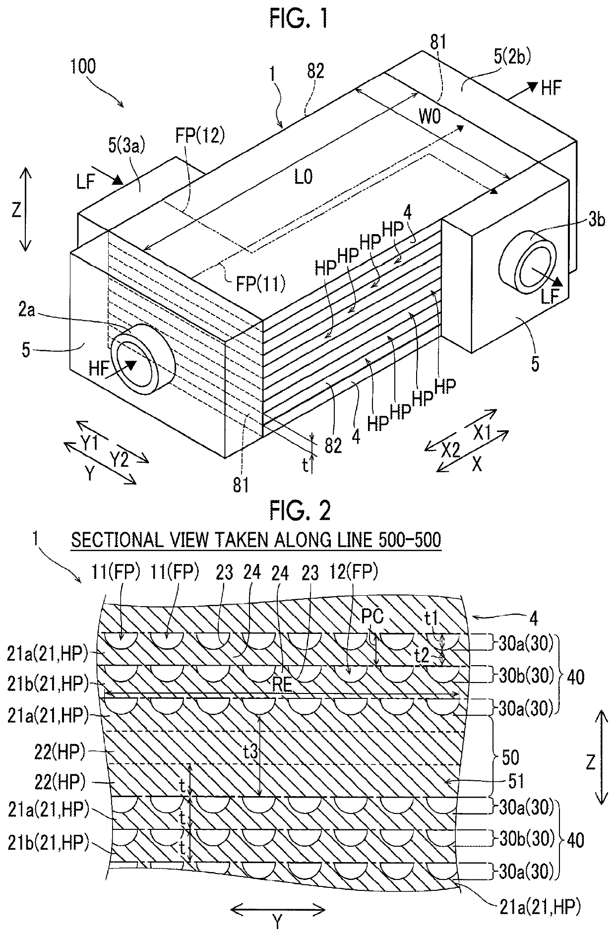
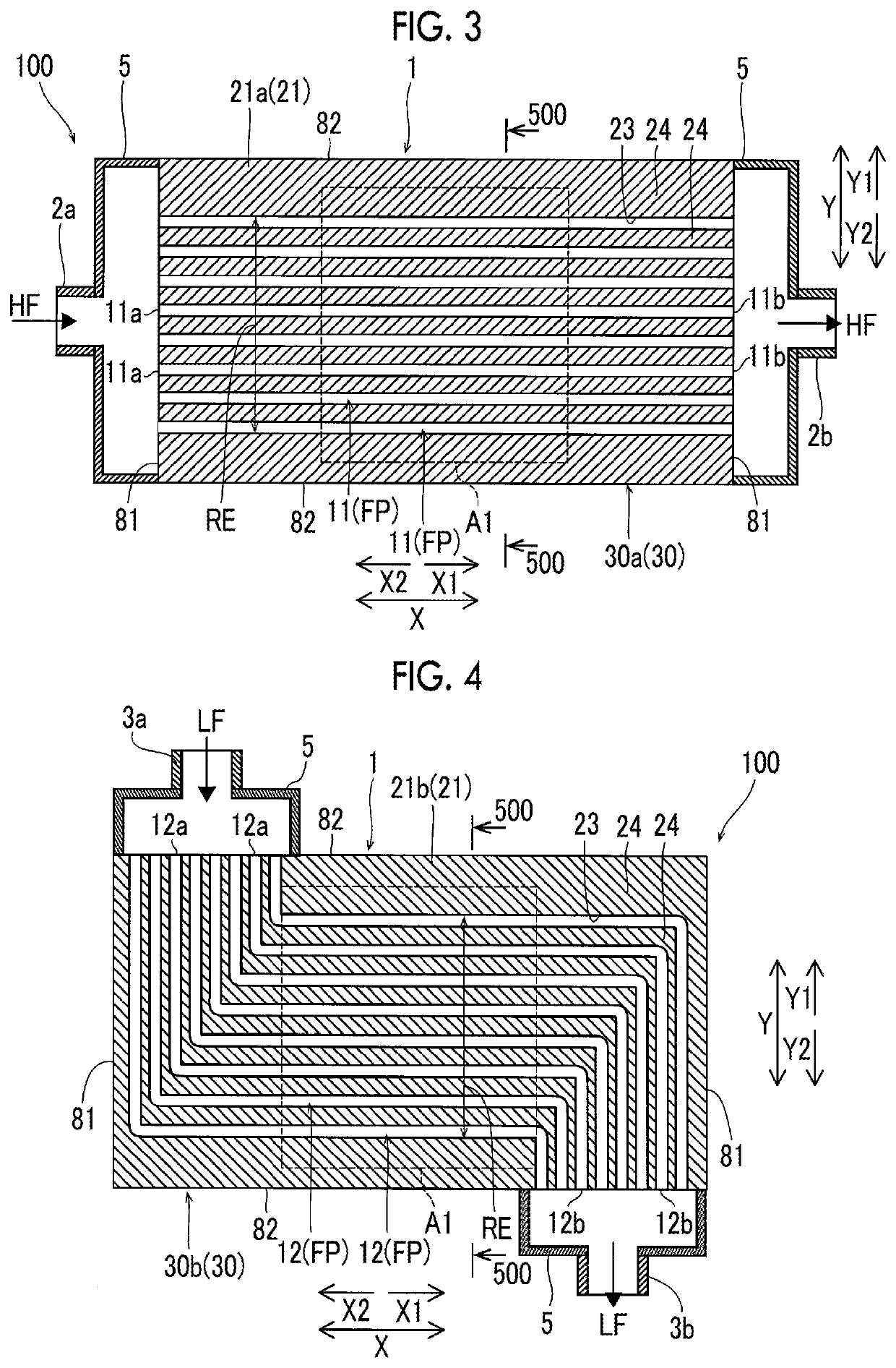
[0102]In the first embodiment, as described above, the partition wall layers 50 are disposed to divide the plurality of flow path blocks 40 each of which is configured to include the plurality of flow path layers 30. Therefore, even in a case where the total number of the flow path layers 30 is increased with an increase in number of stacked heat transfer plates HP to ensure the area of heat transfer, the flow path layers 30 can be divided by the partition wall layers 50 into the plurality of flow path blocks 40 with a smaller number of stacked layers. In addition, since each partition wall layer 50 has the thickness t3 that is larger than the interval t2 between the flow paths FP arranged in the stacking direction, the partition wall layer 50 can ensure a high rigidity in comparison with a case where the flow path layers 30 are simply stacked. Therefore, in the partition wall la...
second embodiment
Effect of Second Embodiment
[0118]In the second embodiment as well, as in the first embodiment, the partition wall layers 50 are disposed to divide the plurality of flow path blocks 40 each of which is configured to include the plurality of flow path layers 30 and each partition wall layer 50 has the thickness t3 that is larger than the interval t2 between the flow paths FP arranged in the stacking direction. Therefore, even in a case where the number of stacked heat transfer plates HP is made large, a thermal stress generated due to heat exchange between fluids significantly different from each other in temperature can be reduced.
[0119]In addition, in the second embodiment, the flow path layers 30 are composed of the first heat transfer plates 21 and the third heat transfer plates 25 and the partition wall layers 50 are composed of the portions of the third heat transfer plates 25 excluding the groove portions 23. Therefore, it is possible to collectively configure the flow path lay...
modification example
[0121]Note that, the embodiments disclosed herein are merely illustrative in all aspects and should not be recognized as being restrictive. The scope of the present invention is defined by the scope of the claims instead of the description in the embodiments, and is intended to include meaning equivalent to the scope of the claims and all modifications (modification examples) within the scope.
[0122]For example, in the first and second embodiments, an example in which the inlet temperature of the high-temperature fluid HF is approximately the same as an environmental temperature (approximately 20° C.) and the inlet temperature of the low-temperature fluid LF is −253° C., which is a very low temperature, has been described. However, the present invention is not limited thereto. For example, the high-temperature fluid HF may have a very high temperature with the low-temperature fluid LF having a temperature close to the environmental temperature and the high-temperature fluid HF may ha...
PUM
| Property | Measurement | Unit |
|---|---|---|
| temperature | aaaaa | aaaaa |
| temperature | aaaaa | aaaaa |
| temperature | aaaaa | aaaaa |
Abstract
Description
Claims
Application Information
 - R&D
- Intellectual Property
- Life Sciences
- Materials
- Tech Scout
- Unparalleled Data Quality
- Higher Quality Content
- 60% Fewer Hallucinations
Browse by: Latest US Patents, China's latest patents, Technical Efficacy Thesaurus, Application Domain, Technology Topic, Popular Technical Reports.
© 2025 PatSnap. All rights reserved.Legal|Privacy policy|Modern Slavery Act Transparency Statement|Sitemap|About US| Contact US: help@patsnap.com