Rotating electrical machine
a technology of rotating electrical machines and rotating shafts, which is applied in the direction of rotating parts of magnetic circuits, magnetic circuit shapes/forms/construction, windings, etc., can solve the problems of local effective decrease, decrease in mechanical strength of magnetic steel plates, and risk of damage to magnetic steel plates, so as to minimize the risk of a drop in output torque and minimize the risk of breakage of magnet retainers
- Summary
- Abstract
- Description
- Claims
- Application Information
AI Technical Summary
Benefits of technology
Problems solved by technology
Method used
Image

Examples
first embodiment
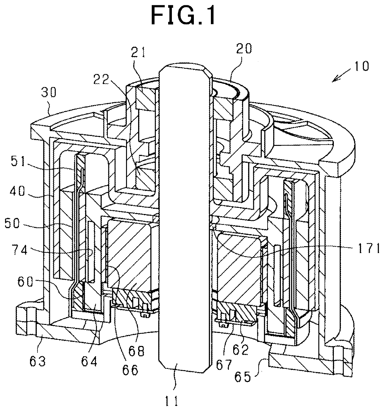
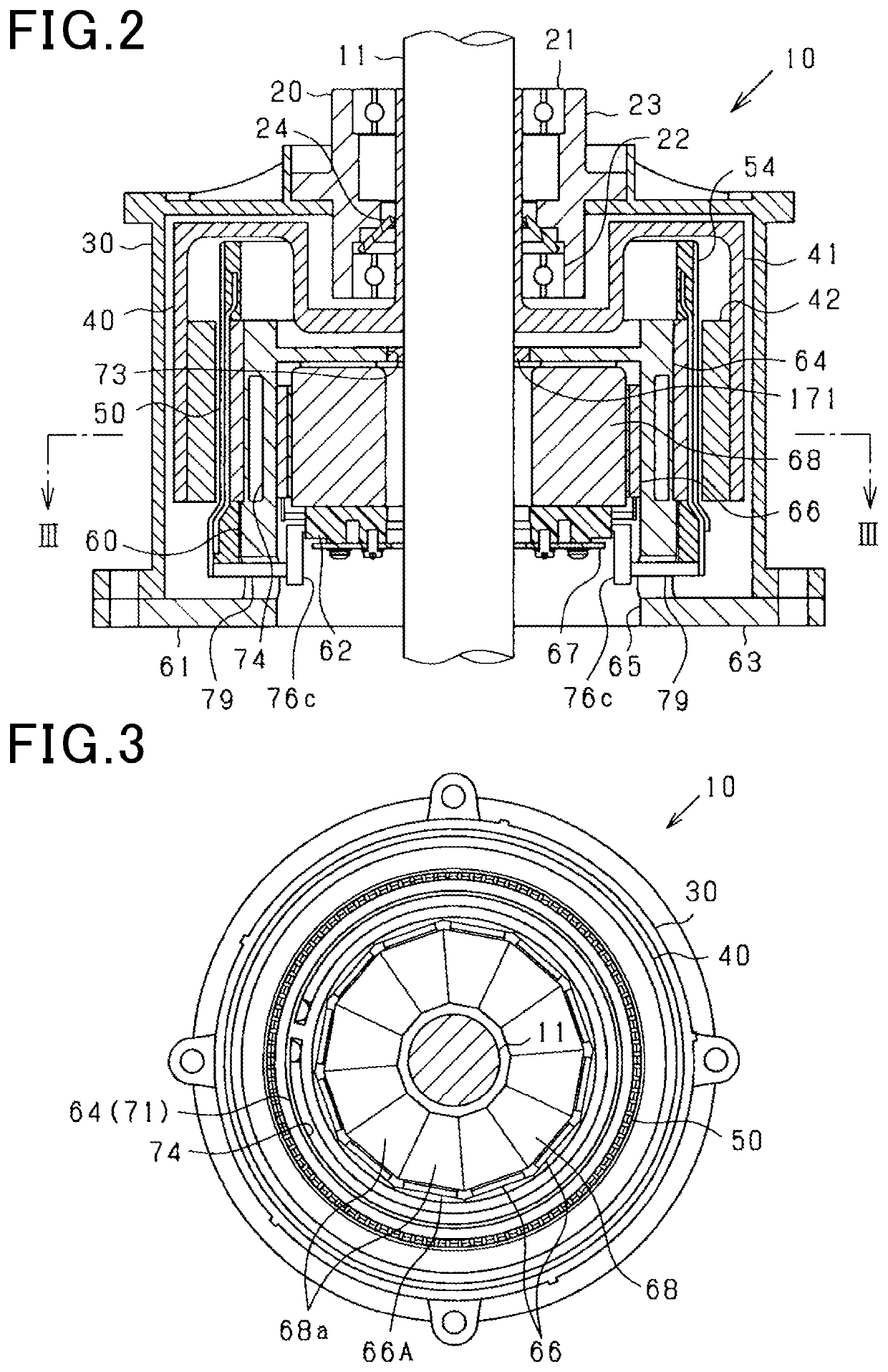
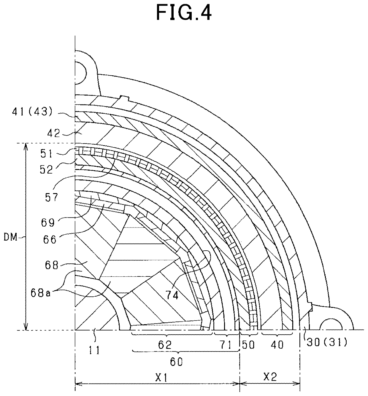
[0102]The rotating electrical machine 10 in this embodiment is a synchronous polyphase ac motor having an outer rotor structure (i.e., an outer rotating structure). The outline of the rotating electrical machine 10 is illustrated in FIGS. 1 to 5. FIG. 1 is a perspective longitudinal sectional view of the rotating electrical machine 10. FIG. 2 is a longitudinal sectional view along the rotating shaft 11 of the rotating electrical machine 10. FIG. 3 is a transverse sectional view (i.e., sectional view taken along the line III-III in FIG. 2) of the rotating electrical machine 10 perpendicular to the rotating shaft 11. FIG. 4 is a partially enlarged sectional view of FIG. 3. FIG. 5 is an exploded view of the rotating electrical machine 10. FIG. 3 omits hatching showing a section except the rotating shaft 11 for the sake of simplicity of the drawings. In the following discussion, a lengthwise direction of the rotating shaft 11 will also be referred to as an axial direction. A radial dire...
second embodiment
[0273]In this embodiment, the polar anisotropic structure of the magnet unit 42 of the rotor 40 is changed and will be described below in detail.
[0274]The magnet unit 42 is, as clearly illustrated in FIGS. 22 and 23, made using a magnet array referred to as a Halbach array. Specifically, the magnet unit 42 is equipped with the first magnets 131 and the second magnets 132. The first magnets 131 have a magnetization direction (i.e., an orientation of a magnetization vector thereof) oriented in the radial direction of the magnet unit 42. The second magnets 132 have a magnetization direction (i.e., an orientation of the magnetization vector thereof) oriented in the circumferential direction of the magnet unit 42. The first magnets 131 are arrayed at a given interval away from each other in the circumferential direction. Each of the second magnets 132 is disposed between the first magnets 131 arranged adjacent each other in the circumferential direction. The first magnets 131 and the sec...
first modification
[0288]In the above embodiment, the outer peripheral surface of the stator core 52 has a curved surface without any irregularities. The plurality of conductor groups 81 are arranged at a given interval away from each other on the outer peripheral surface of the stator core 52. This layout may be changed. For instance, the stator core 52 illustrated in FIG. 25 is equipped with the circular ring-shaped yoke 141 and the protrusions 142. The yoke 141 is located on the opposite side (i.e., a lower side, as viewed in the drawing) of the stator winding 51 to the rotor 40 in the radial direction. Each of the protrusions 142 protrudes into a gap between a respective two of the straight sections 83 arranged adjacent each other in the circumferential direction. The protrusions 142 are arranged at a given interval away from each other in the circumferential direction radially outside the yoke 141, i.e., close to the rotor 40. Each of the conductor groups 81 of the stator winding 51 engages the p...
PUM
 Abstract
Description
Claims
Application Information
 - R&D
- Intellectual Property
- Life Sciences
- Materials
- Tech Scout
- Unparalleled Data Quality
- Higher Quality Content
- 60% Fewer Hallucinations
Browse by: Latest US Patents, China's latest patents, Technical Efficacy Thesaurus, Application Domain, Technology Topic, Popular Technical Reports.
© 2025 PatSnap. All rights reserved.Legal|Privacy policy|Modern Slavery Act Transparency Statement|Sitemap|About US| Contact US: help@patsnap.com