
Electrode

a technology of electrodes and electrodes, applied in the field of electrodes, can solve the problems of expensive and elaborate operation of coating the eyelet (connecting element) and achieve the effect of reducing the cost and complexity of the operation

Pending Publication Date: 2022-02-03
LEONH LANG
View PDF0 Cites 0 Cited by
  • Summary
  • Abstract
  • Description
  • Claims
  • Application Information

AI Technical Summary

Benefits of technology

The invention provides a way to connect a signal conductor to an electrode while using less expensive materials. Instead of coating the entire eyelet with a conductor, only the small part in contact with the contact medium is affected. This results in less silver conversion and slow conversion from edge layers to covered regions, reducing costs. A deformed enlarged region of the holding element ensures a good hold on the carrier or conductor, even with pressure loadings. The conductor can be introduced without a through opening, saving on a working step. An electrically conducting material can be used at the transition region to the electrical contact medium, using inexpensive materials like metal or plastic. Overall, the invention provides a cost-effective solution for connecting an electrode to a signal conductor.

Problems solved by technology

In that way, it is possible for the expensive and elaborate operation of coating the entire eyelet (connecting element) with for example silver / silver chloride to be replaced by the substantially less expensive conductor which is easy to produce.

Method used


Image

  • Electrode
  • Electrode
  • Electrode

Examples


Embodiment Construction

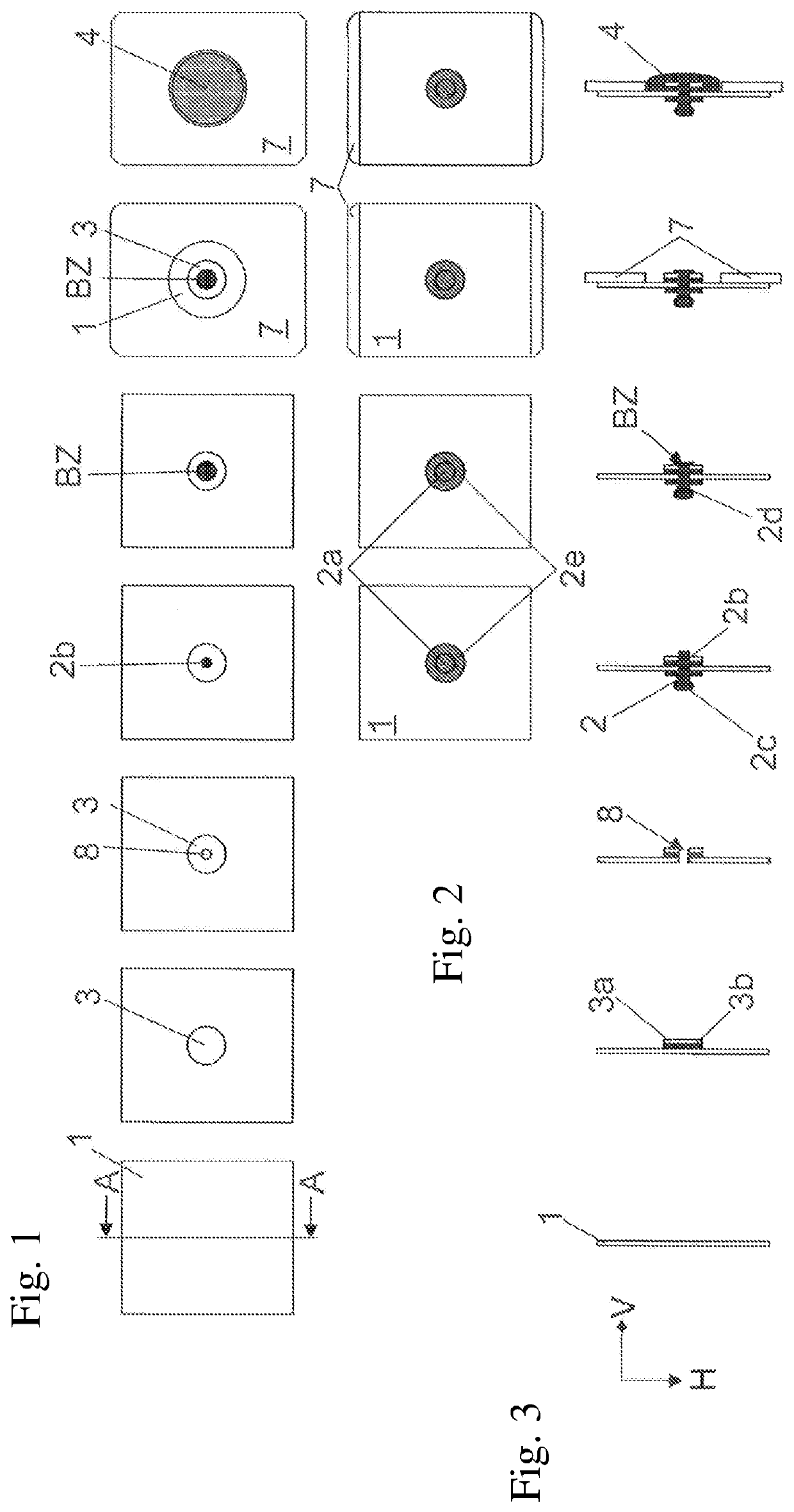
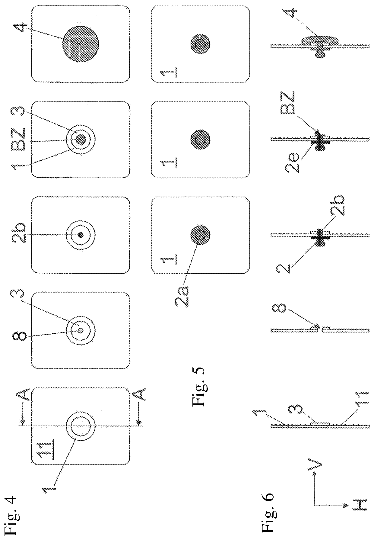
[0052]With reference to FIGS. 1 through 3 the procedure of the method for the production of an embodiment of an electrode according to the invention for application to the human skin is now described in greater detail.

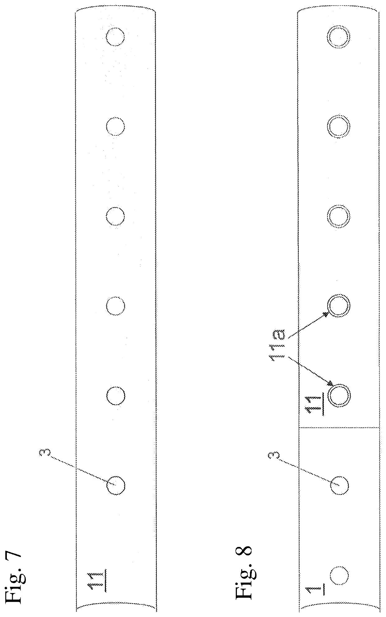
[0053]The basic starting point is an electrically non-conducting carrier 1. The carrier material serves for anchoring the electrical components of the electrode. It can comprise for example a (flexible) film (for example of PET or TPU) which on the underside facing upwardly in the drawing of FIG. 1 is completely or partially coated with an adhesive which for example can be self-adhesive (pressure sensitive adhesive) or thermoactivatable (hot melt).

[0054]Now in a next step a rotationally symmetrical conductor 3 is fixed on that carrier material, preferably by adhesive or by being printed thereon. In accordance with a preferred variant of the invention the conductor has two differently electrically conducting materials or an electrically non-conducting material 3b and an...


PUM


Abstract

An electrode includes an electrically non-conductive support. A protruding, electrically conductive attachment element with an attachment site for the releasable attachment of a signal conductor is on an upper face of the support. A conductor is on the underside of the support, and is electrically connected to the attachment element and to a contact medium. The conductor and the contact medium are arranged on the underside of the support. An imaginary normal to the support, running through the attachment element, runs through the conductor or a recess in the conductor and through the contact medium or a recess in the contact medium. The conductor has on its surface a redox pair suitable for the depolarization of the electrode. The attachment element has a projection reaching through the support with a widened region at its end, and the conductor is arranged between the widened region and the support.

Description

BACKGROUND OF THE INVENTION[0001]The invention concerns an electrode and a method of producing an electrode.[0002]Medical skin electrodes of that kind can be used as measurement electrodes which derive electrical signals from the human body. They can however also be used as therapy electrodes to feed currents to the human body. For that purpose the electrodes are glued on to the skin and on their underside generally have an electrically conducting gel or another electrical contact medium which is galvanically in contact with a connecting element of the electrode. An electrical signal conductor can be connected to that connecting element, by way of which conductor currents can be taken from the electrode or fed to the electrode.[0003]One type of electrode has at the top side facing away from the skin a projecting electrically conducting connecting element with a generally substantially ball head-shaped connecting location to which a neck is connected.[0004]In the previous constructio...

Claims


Application Information

Patent Timeline
IPC IPC(8): A61B5/265A61B5/268A61B5/259A61B5/274A61B5/296
CPCA61B5/265A61B5/268A61B2562/125A61B2562/227A61B2562/0215A61B5/259A61B2562/0217A61B2562/225A61B2560/0468A61B5/274A61B5/291A61B5/296
Inventor KUPSA, THOMAS
Owner LEONH LANG
Learn More