
Ion implantation system and linear accelerator having novel accelerator stage configuration

a technology of ion implantation and accelerator stage, which is applied in the direction of accelerators, plasma techniques, electric discharge tubes, etc., can solve the problems of complex design of accelerator stage in rf-linacs of known ion implantation systems, and achieve the effect of high ion energy

Active Publication Date: 2022-02-03
APPLIED MATERIALS INC
View PDF0 Cites 4 Cited by
  • Summary
  • Abstract
  • Description
  • Claims
  • Application Information

AI Technical Summary

Benefits of technology

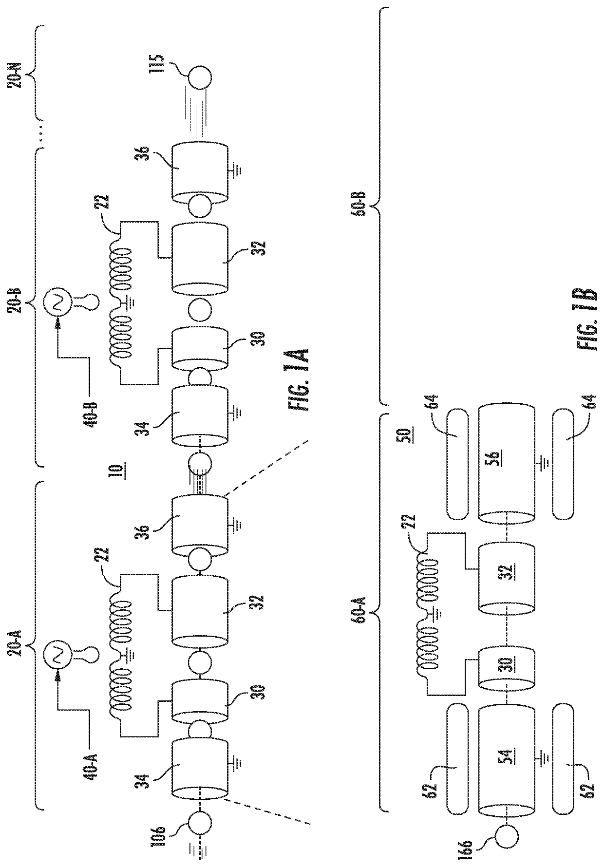
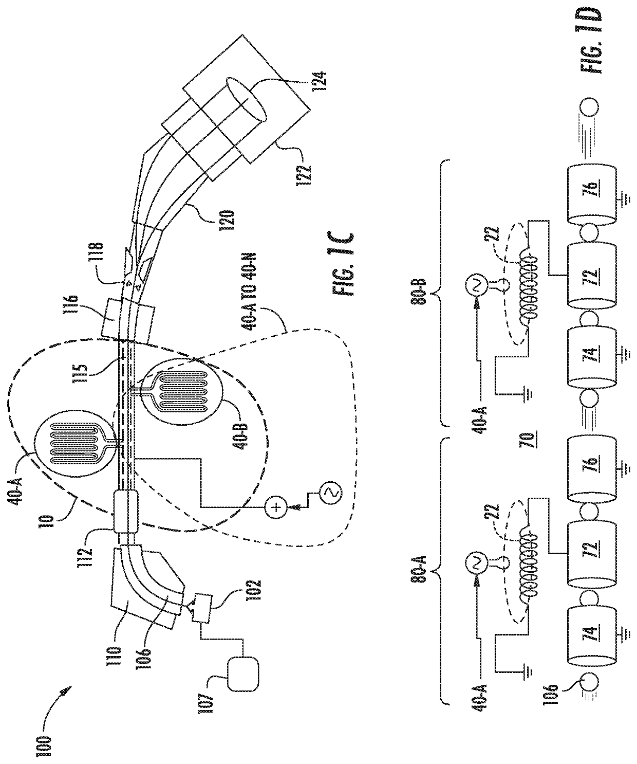
The patent describes novel ion implantation apparatus including an ion source, extraction system, and a linear accelerator with multiple acceleration stages. The ion beam is initially generated and then bunched, and each bunched ion packet is accelerated through a unique acceleration stage that includes a drift tube assembly and a resonator. The resulting ion beam has a high energy and is used to implant into a substrate with reduced energy loss. This invention provides improved performance and efficiency of ion implantation.

Problems solved by technology

However, the design of acceleration stages in RF-LINACS of known ion implantation systems is rather complex.

Method used


Image

  • Ion implantation system and linear accelerator having novel accelerator stage configuration
  • Ion implantation system and linear accelerator having novel accelerator stage configuration
  • Ion implantation system and linear accelerator having novel accelerator stage configuration

Examples


Embodiment Construction

[0022]An apparatus, system and method in accordance with the present disclosure will now be described more fully hereinafter with reference to the accompanying drawings, where embodiments of the system and method are shown. The system and method may be embodied in many different forms and are not be construed as being limited to the embodiments set forth herein. Instead, these embodiments are provided so this disclosure will be thorough and complete, and will fully convey the scope of the system and method to those skilled in the art.

[0023]Terms such as “top,”“bottom,”“upper,”“lower,”“vertical,”“horizontal,”“lateral,” and “longitudinal” may be used herein to describe the relative placement and orientation of these components and their constituent parts, with respect to the geometry and orientation of a component of a semiconductor manufacturing device as appearing in the figures. The terminology may include the words specifically mentioned, derivatives thereof, and words of similar ...


PUM


Abstract

An ion implantation system, including an ion source and extraction system, arranged to generate an ion beam at a first energy, and a linear accelerator, disposed downstream of the ion source, the linear accelerator arranged to receive the ion beam as a bunched ion beam accelerate the ion beam to a second energy, greater than the first energy. The linear accelerator may include a plurality of acceleration stages, wherein a given acceleration stage of the plurality of acceleration stages comprises: a drift tube assembly, arranged to conduct the ion beam; a resonator, electrically coupled to the drift tube assembly; and an RF power assembly, coupled to the resonator, and arranged to output an RF signal to the resonator. As such, the given acceleration stage does not include a quadrupole element.

Description

FIELD OF THE DISCLOSURE[0001]The disclosure relates generally to ion implantation apparatus and more particularly to high energy beamline ion implanters.BACKGROUND OF THE DISCLOSURE[0002]Ion implantation is a process of introducing dopants or impurities into a substrate via bombardment. Ion implantation systems may comprise an ion source and a series of beam-line components. The ion source may comprise a chamber where ions are generated. The ion source may also comprise a power source and an extraction electrode assembly disposed near the chamber. The beam-line components, may include, for example, a mass analyzer, a first acceleration or deceleration stage, a collimator, and a second acceleration or deceleration stage.[0003]Implantation apparatus capable of generating ion energies of approximately 1 MeV or greater are often referred to as high energy ion implanters, or high energy ion implantation systems. One type of high energy ion implanter employs what is termed linear accelera...

Claims


Application Information

Patent Timeline
Patent Type & Authority Applications(United States)
IPC IPC(8): H01J37/317H01J37/32
CPCH01J37/3171H01J37/32247H01J37/32082H01J2237/04735H01J37/3007H05H2277/12H05H9/041
Inventor SINCLAIR, FRANK
Owner APPLIED MATERIALS INC
Learn More