
Energy conversion device with a cryogenic coil

a technology of energy conversion device and cryogenic coil, which is applied in the direction of superconducting magnet/coil, dc-dc conversion, magnetic bodies, etc., can solve the problems and achieve the effect of relatively large volume and relatively high weigh

Pending Publication Date: 2022-02-24
SHANGHAI JIAO TONG UNIV
View PDF4 Cites 0 Cited by
  • Summary
  • Abstract
  • Description
  • Claims
  • Application Information

AI Technical Summary

Benefits of technology

The present invention solves the problems of existing cryogenic coil open-loop excitation technology by reducing heat generation, improving cooling efficiency, and allowing for easier operation with high-temperature superconducting materials. Compared to prior art, the present invention has lower heating power on the current lead, avoids the dependence on ultra-low resistance or superconducting joints, and can obtain a higher operating current with less superconducting material. The power electronic converter in the present invention can output direct current and interact with the external alternating magnetic field provided by an electromagnet with an iron core to generate dynamic resistance at the closed coil, and achieve faster excitation speed and more convenient energy feedback to the superconducting coil.

Problems solved by technology

When the power is high and the frequency is low, the weight is relatively high and the volume is relatively large; some types of magnetic flux pumps cannot achieve energy feedback.

Method used


Image

  • Energy conversion device with a cryogenic coil
  • Energy conversion device with a cryogenic coil
  • Energy conversion device with a cryogenic coil

Examples


Embodiment Construction

[0086]Hereinafter, several preferred embodiments of the present invention will be introduced with reference to the drawings in the specification, so that the technical content will be clearer and easier to understand. The present invention can be embodied by many different forms of embodiments, and the protection scope of the present invention is not limited to the embodiments mentioned in the text.

[0087]In the drawings, components with the same structure are represented by the same numerals, and components with similar structures or functions are represented by similar numerals or text numerals. The size and thickness of each component shown in the drawings are arbitrarily shown, and the present invention does not limit the size and thickness of each component. In order to make the illustration clearer, the thickness of the components is appropriately exaggerated in some places in the drawings.

[0088]The related concepts described in this application document are defined as follows:...


PUM

PropertyMeasurementUnit
current currentaaaaaaaaaa
superconductingaaaaaaaaaa
currentaaaaaaaaaa

Abstract

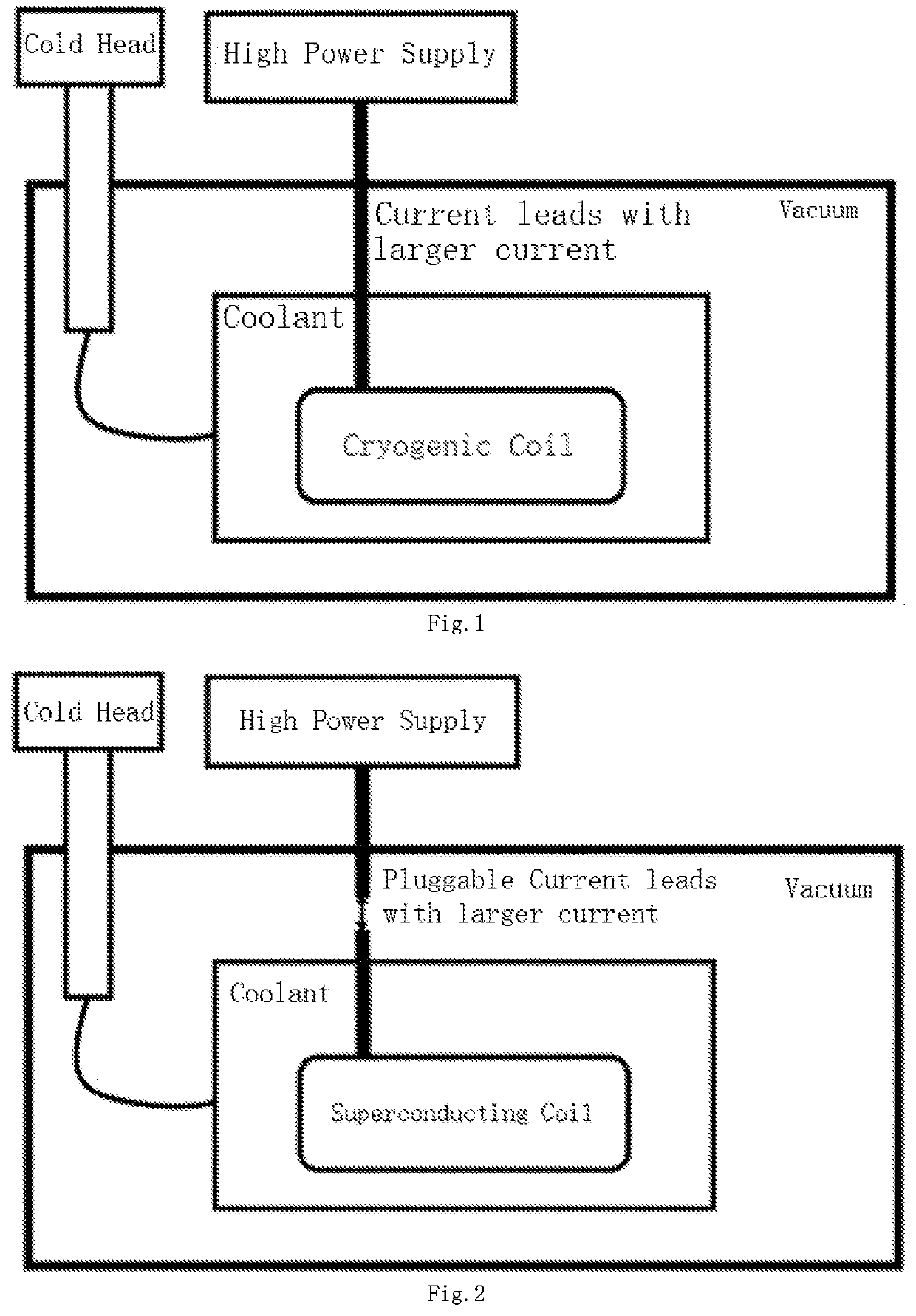
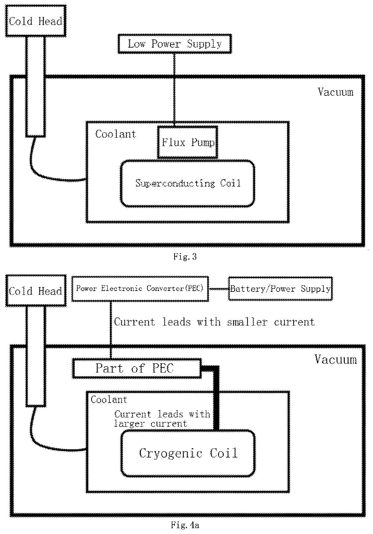
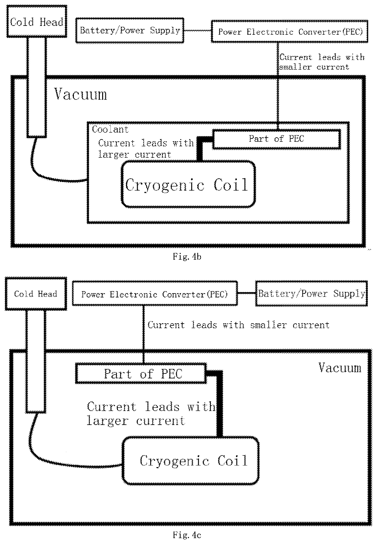
The invention discloses an energy conversion device with a cryogenic coil, which relates to the technical field of electromagnet excitation, the device comprises a cold source module, a vacuum module, an external energy module, an internal energy module and a connection module; the cold source module is configured to provide the cold source to the vacuum module, the external energy module is configured to be located outside the vacuum module, the internal energy module is configured to be located inside the vacuum module, and the internal energy module and the external energy module are configured to be connected through the connection module. The energy conversion device with a cryogenic coil further comprises a coolant module, the coolant module is configured to be located inside the vacuum module, and the internal energy module is configured to be located inside the coolant module. The connection module comprises a power electronic converter.

Description

CROSS-REFERNCE TO RELATED APPLICATIONS[0001]This application is a bypass continuation application of PCT application no.: PCT / CN2020 / 071412. This application claims priorities from PCT Application No. PCT / CN2020 / 071412, filed Jan. 10, 2020, PCT Application No. PCT / CN2019 / 102301, filed Aug. 23, 2019, Chinese patent application 201910023177.6, filed Jan. 10, 2019, and from the Chinese patent application 201910163732.5 filed Mar. 5, 2019, the contents of which are incorporated herein in the entirety by reference.TECHNICAL FIELD[0002]The present invention relates to the field of electromagnet excitation technology, in particular to an energy conversion device with a cryogenic coil.BACKGROUND[0003]The phenomenon of superconductivity was discovered in 1911, and due to its excellent properties, such as zero resistance, it quickly attracted the attention of researchers worldwide. The critical temperature of superconducting materials can reach 20K-77 K or even higher, and some materials can ...

Claims


Application Information

Patent Timeline
Patent Type & Authority Applications(United States)
IPC IPC(8): H01F6/06H02M5/458H01F6/04H02M7/00
CPCH01F6/06H02M7/003H01F6/04H02M5/4585H02J50/10H01F6/008H02M3/33584H02M7/5387H05K7/20H02M3/158H02M1/007H02M3/156H02M3/33507H02M3/1582Y02E40/60
Inventor HUANG, ZHEN
Owner SHANGHAI JIAO TONG UNIV
Learn More