Macro and micro inspection apparatus and inspection method

a micro- and micro-scale technology, applied in the field of micro- and micro-scale inspection apparatus and inspection methods, can solve the problems of increasing the time required for the overall inspection process, occupying space, and material loss, and achieve the effect of high inspection efficiency

Pending Publication Date: 2022-03-10
MICROELECTRONICS TECH INC
View PDF0 Cites 1 Cited by
  • Summary
  • Abstract
  • Description
  • Claims
  • Application Information

AI Technical Summary

Benefits of technology

[0004]The present invention has been accomplished in view of the above-noted circumstances. It is an objective of the present invention to provide a macro and micro inspection apparatus and an inspection method thereof, which can avoid problems caused by manual inspection, and the inspection apparatus is structurally simple, space-saving, and brings high inspection efficiency.
[0010]As a result, the macro and micro inspection apparatus and the inspection method of the present invention only need a robot arm to transfer the device under test between the device under test storage station, the macro inspection station and the micro inspection station. Besides, the various actions the quality inspector performs for the macro inspection can be simulated in the macro inspection station by the robot arm performing various actions to the device under test, such as displacing, tilting, rotating, and so on, and cooperating with the visual recognition system, so as to attain the front inspection, back inspection, lateral inspection, oblique inspection, rotary inspection, light refection inspection, and so on. Therefore, the present invention doesn't need human labor to transfer the device under test or inspect the appearance of the device under test by the naked eyes, thereby prevented from the problems of missed inspection, false inspection, wafer falling, wafer collision, and so on, which may be caused by manual inspection. Besides, the present invention can steadily repeat the same macro inspection actions to attain great inspecting effect. Furthermore, the macro and micro inspection apparatus of the present invention is quite simple in structure and space-saving, and can connect the macro inspection with different micro inspection procedures or with device under test storage stations for the devices under test of different sizes. Therefore, according to the inspection requirements and the use environment, the most appropriate arrangement can be made to improve the machine utilization and reduce the transferring distance and waiting time between different procedures, thereby bringing high inspection efficiency.

Problems solved by technology

However, the macro inspection performed manually may not only cause missed inspection or false inspection due to visual fatigue of the quality inspector, but also may cause wafer falling or wafer collision due to transporting negligence of the quality inspector, so as to cause material loss.
These procedures not only take up space, but also increase the time required for the overall inspection process.
In other words, the devices provided in the inspection apparatus for moving the device under test include the aforementioned transferring robot and rotary mechanism, which also quite take up space.
Besides, the inspection station is equipped therein with the rotary mechanism, the macro inspection part and the micro inspection part, thereby complicated and crowded in its spatial arrangement.
Therefore, the macro inspection part is also quite complicated in its structure and spatial arrangement.

Method used


Image

  • Macro and micro inspection apparatus and inspection method
  • Macro and micro inspection apparatus and inspection method
  • Macro and micro inspection apparatus and inspection method

Examples


Embodiment Construction

[0023]First of all, it is to be mentioned that same or similar reference numerals used in the following embodiments and the appendix drawings designate same or similar elements or the structural features thereof throughout the specification for the purpose of concise illustration of the present invention. It should be noticed that for the convenience of illustration, the components and the structure shown in the figures are not drawn according to the real scale and amount, and the features mentioned in each embodiment can be applied in the other embodiments if the application is possible in practice.

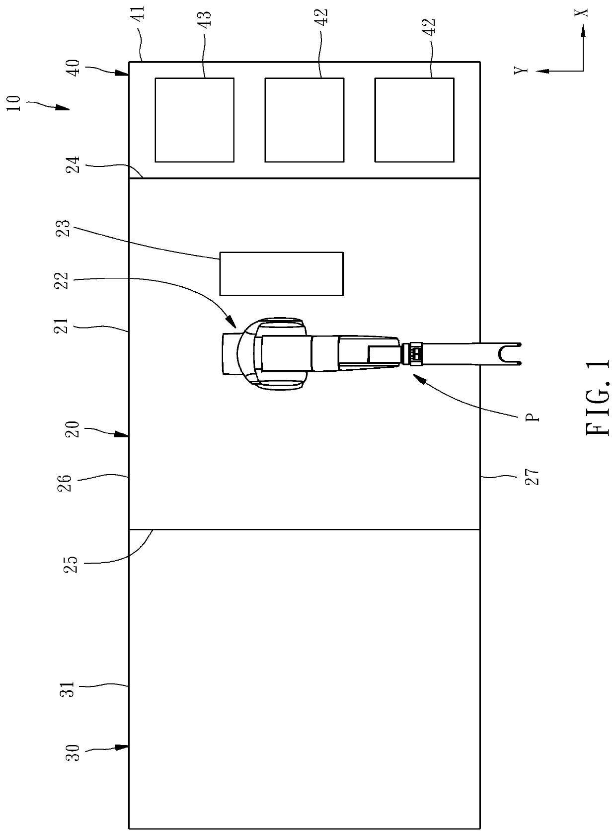
[0024]Referring to FIG. 1, a macro and micro inspection apparatus 10 according to a first preferred embodiment of the present invention includes a macro inspection station 20, a micro inspection station 30, and a device under test storage station 40.

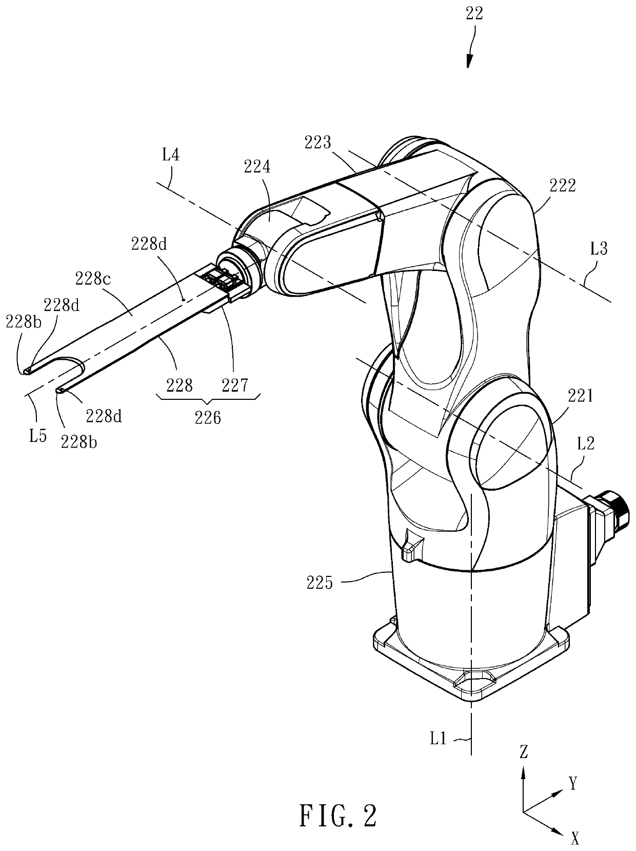
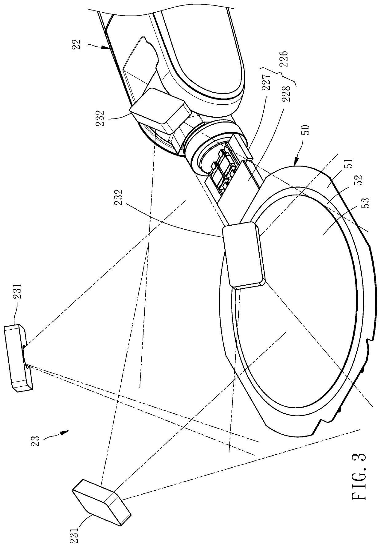
[0025]The macro inspection station 20 includes a housing 21, and a robot arm 22 and a visual recognition system 23 disposed in the housing 2...


PUM

PropertyMeasurementUnit
optical inspectionaaaaaaaaaa
sizesaaaaaaaaaa
electrical propertiesaaaaaaaaaa

Abstract

A macro and micro inspection apparatus includes a macro inspection station including a housing, a robot arm and a visual recognition system, and a device under test storage station and a micro inspection station disposed on two sides of the macro inspection station, respectively. The robot arm including an end effector adapted for carrying and turning over a device under test is disposed in the housing in a way that the end effector enables to enter the device under test storage station and the micro inspection station. The visual recognition system includes at least one image capturing device disposed in the housing for shooting toward the end effector for capturing the image of the device under test. The invention, which also provides an inspection method using the inspection apparatus, is structurally simple, space-saving, avoids problems caused by manual inspection, and brings high inspection efficiency.

Description

BACKGROUND OF THE INVENTION1. Field of the Invention[0001]The present invention relates generally to electronic component inspection apparatus and more particularly, to an inspection apparatus which integrates macro inspection and micro inspection, and an inspection method thereof.2. Description of the Related Art[0002]In the conventional wafer inspection process, macro inspection is usually performed first. That is, a quality inspector observes the wafer by naked eyes and determines whether the appearance of the wafer is flawed. If the appearance of the wafer is flawless, micro inspection is then performed. That is, an inspection instrument is used to inspect the appearance, the electrical properties and / or optical characteristics of the dies of the wafer. However, the macro inspection performed manually may not only cause missed inspection or false inspection due to visual fatigue of the quality inspector, but also may cause wafer falling or wafer collision due to transporting neg...

Claims


Application Information

Patent Timeline
Patent Type & Authority Applications(United States)
IPC IPC(8): G01N21/88G01N21/95B25J11/00H04N5/247
CPCG01N21/8851H04N5/247B25J11/0095G01N21/9501G01N21/01G01N2021/0106B25J15/0014B25J15/0616H04N23/698H04N25/41H04N23/90
Inventor TSAI, CHEN-YANGCHEN, WEI-MAOHSIEH, HUAN-CHUN
Owner MICROELECTRONICS TECH INC
Why Eureka
Try Eureka