Plant and method for accumulation of energy in thermal form

a technology of energy storage and plant, applied in the field of plants and methods for the accumulation of energy in thermal form, can solve the problems of not being able to store important energy levels and the capacity of accumulation of energy, and achieve the effect of zero environmental impa

Pending Publication Date: 2022-03-24
MAGALDI POWER SPA
View PDF0 Cites 12 Cited by
  • Summary
  • Abstract
  • Description
  • Claims
  • Application Information

AI Technical Summary

Benefits of technology

[0043]Another advantage of the proposed system is the independence from the latitude, since it can be installed in any country in the world, unde...

Problems solved by technology

In order to solve the above-mentioned drawbacks, sometimes one has recourse to electrochemical batteries which however do not allow to store important energy levels.
Moreover, some used electrochemical accumulation systems are the most critical element of the whole production system, above all due to their short useful life, the high investment cost with respect to performances, the dependence of the...

Method used


Image

  • Plant and method for accumulation of energy in thermal form
  • Plant and method for accumulation of energy in thermal form
  • Plant and method for accumulation of energy in thermal form

Examples


first embodiment

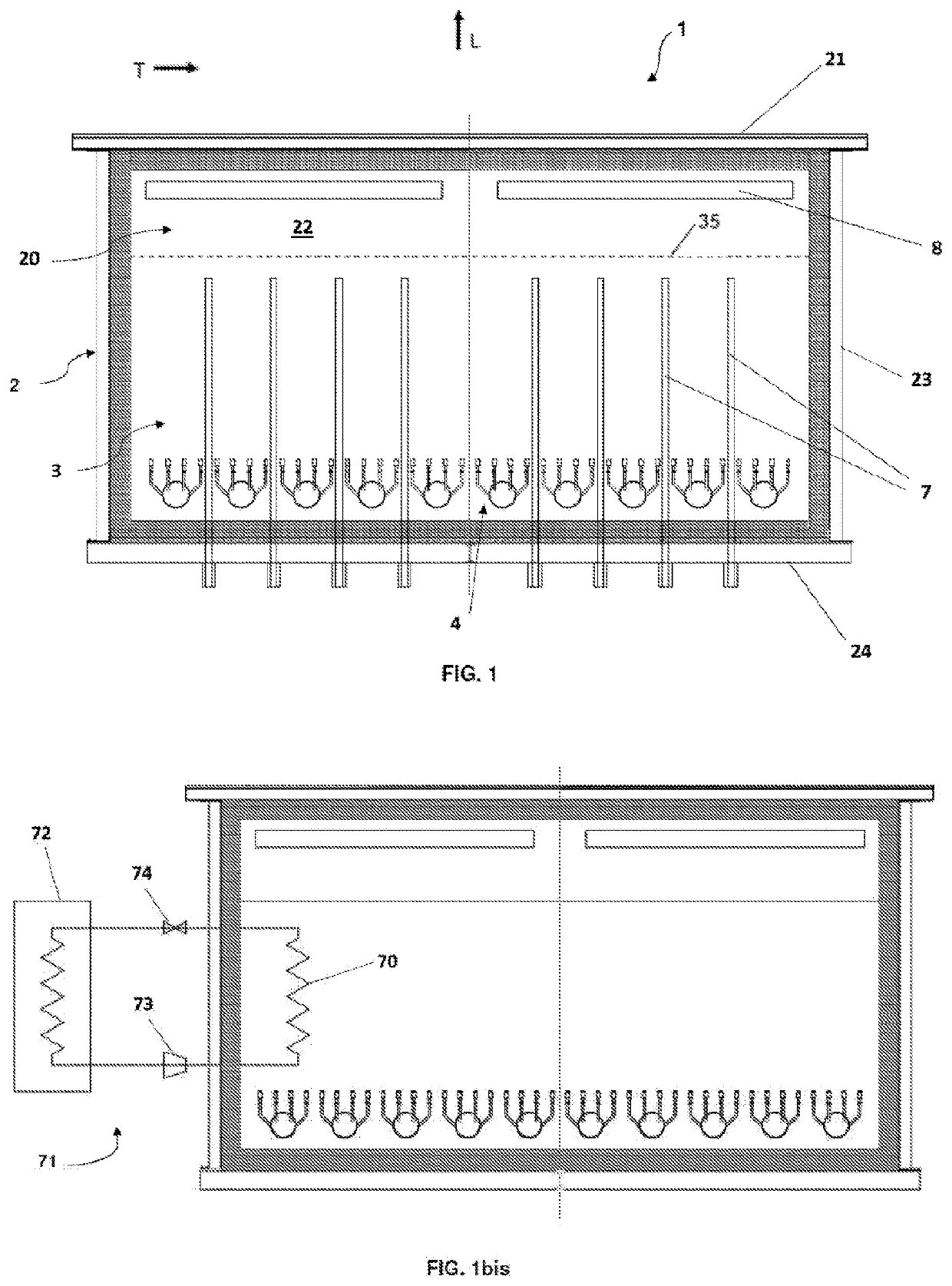
[0101]FIG. 3 relates to a third preferred embodiment of the device of the invention, herein designated with 100. With respect to the device described with reference to the first embodiment and relative above-illustrated variants, the device 100 has an irradiation opening 10 at the upper wall 21 of the casing 2. A (not illustrated) optical system, associated to the device 100, concentrates the incident solar radiation indeed inletting such opening 10 and within the compartment 20. In this way, the particles of the bed 3 absorb primary thermal energy, of solar origin.

[0102]In the present example, the opening 10 is shown as arranged at the upper wall 21 of the casing 2 and preferably centred longitudinally with respect thereto. Embodiment variants can provide a different positioning thereof. In the same way, the opening 10, under operating conditions, can be wholly open towards outside, without shielding or covering means, or it can have a protection window transparent to the incident ...

fourth embodiment

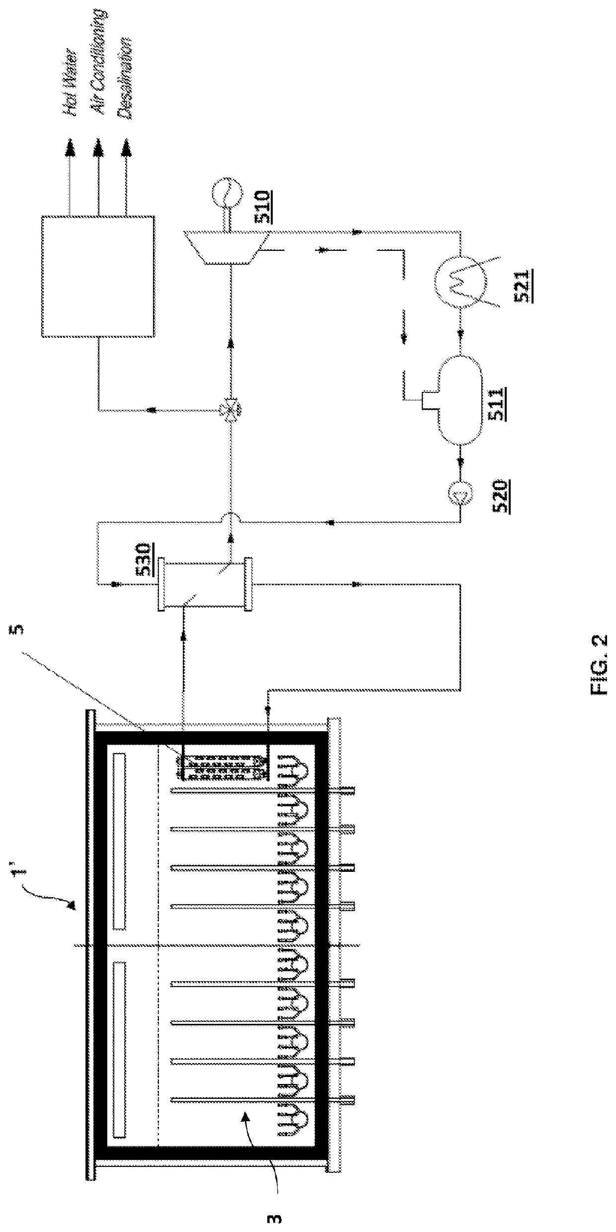
[0114]With reference to FIG. 4, this illustrates schematically the device of the invention, herein designated with 100′. Similarly to the configuration of FIG. 2, the device 100′ is different from the one described with reference to FIG. 3 due to the fact of having further heat exchange elements housed within the bed 3, in particular tube bundles 5. The configuration of said tube bundles and of further plant components associated thereto is the same already described above indeed with reference to FIG. 2.

[0115]The auxiliary device 9 can be independent from the heat exchange elements 5 immersed into the bed of particles or it can be connected thereto.

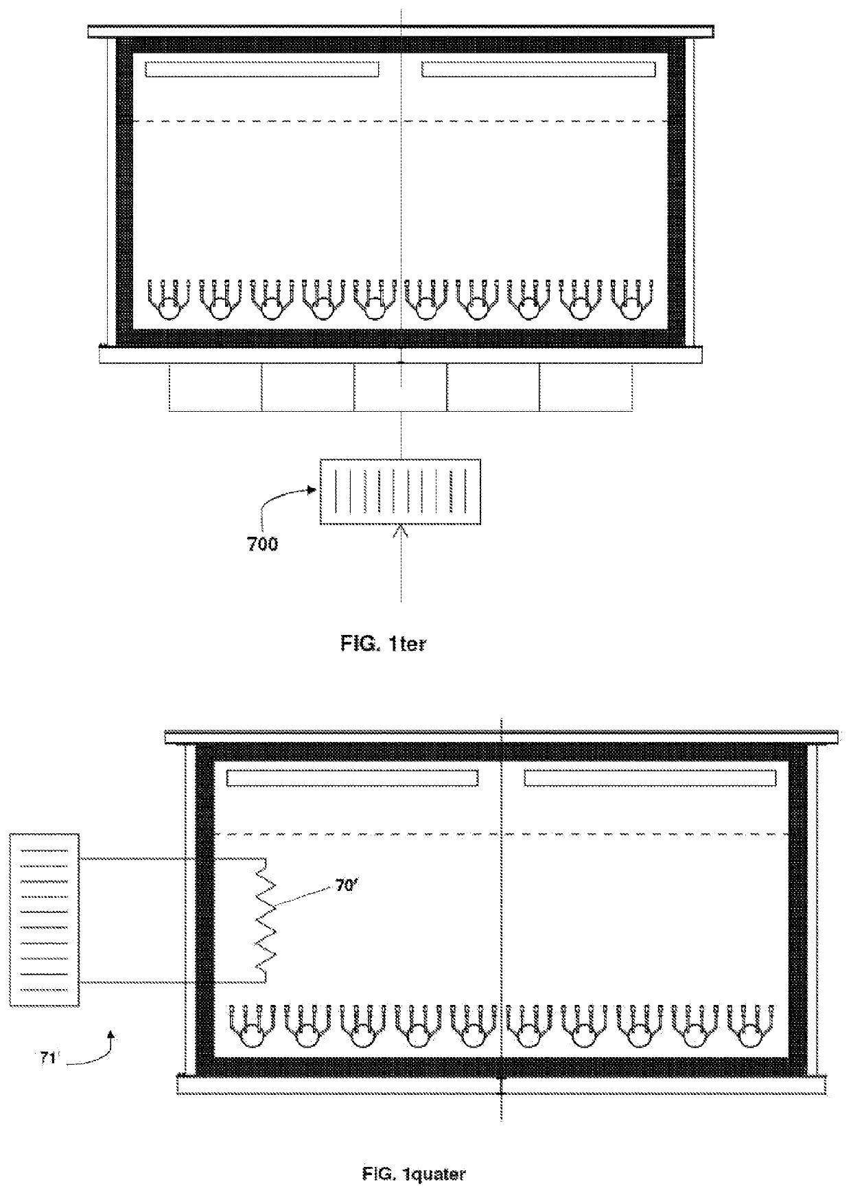
[0116]The FIGS. 4bis, 4ter and 4quater show each one a respective embodiment variant of the device of FIG. 4, wherein the electric resistors 7 are replaced by several heating means or components of the bed of particles, indeed configured to convert an inlet energy, particularly electric energy, into heating thermal energy of the bed of p...


PUM


Abstract

A plant for the accumulation and transfer of thermal energy, which plant has an accumulation device of the kind with a bed of fluidizable solid particles. The plant further has for each accumulation device:
    • electric resistor means arranged within the casing and thermally connected with the bed of particles, which electric resistors are configured for transmitting thermal energy generated by Joule effect to the particles and they are fed by exceeding electric energy from wind or photovoltaic source; and
    • heat exchange means, also thermally connected with the bed of particles and which can be selectively actuated to receive thermal energy therefrom,
the overall configuration being such that the thermal energy is transferred from the resistor means to the fluidizable solid particles of the bed and from the fluidizable solid particles to the heat exchange means.

Description

TECHNICAL FIELD OF THE INVENTION[0001]The present invention mainly relates to a plant and a method for the accumulation of energy in thermal form. In particular, the invention uses devices for the accumulation of thermal energy which use a bed of fluidizable solid particles.[0002]State of art Low-cost plants for the production of electric energy from renewable source, in particular of photovoltaic and wind type, are known.[0003]In the last ten year, the use of photovoltaic plants in Italy and all over the world has significantly increased, and of the wind component as well, even and above all in view of decarbonisation (use of energy sources free from atmospheric emissions of CO2). With the increasing component of production from renewable sources for their discontinuous nature, like indeed wind and sun, situations are more and more often determined wherein, during some time periods an excess of not exploited energy availability occurs, to the detriment of the overall exploitation o...

Claims


Application Information

Patent Timeline
IPC IPC(8): F24S60/00F24S20/20F24S23/00F24S80/40F24S20/40F24S80/20
CPCF24S60/00F24S20/20F24S80/20F24S80/40F24S20/40F24S23/00Y02P80/20F28D20/0056F28D2020/0021F28D2020/006F28D13/00F01K3/186F03G6/065F03G7/04Y02E10/44Y02E20/14Y02E60/14Y02E10/40
Inventor MAGALDI, MARIOBASSETT!, FULVIO
Owner MAGALDI POWER SPA
Why Eureka
Try Eureka