
Inkjet head, method of manufacturing inkjet head, and inkjet recording method

a technology of inkjet recording and inkjet head, which is applied in the direction of printing, inking apparatus, etc., can solve the problems of ink resistance, ink resistance and adhesiveness, and the gradual eroded base film of the liquid-repellent layer by the alkaline ink, so as to improve the ink resistance and adhesiveness, and improve the ink resistance and adhesion.

Pending Publication Date: 2022-04-07
KONICA MINOLTA INC
View PDF0 Cites 0 Cited by
  • Summary
  • Abstract
  • Description
  • Claims
  • Application Information

AI Technical Summary

Benefits of technology

The present invention provides an inkjet head with a nozzle plate that is resistant to ink and easy to adhere to. The nozzle plate is formed by a liquid-repellent layer base film that is stable even when exposed to different types of ink. Additionally, the invention provides a method for manufacturing the nozzle plate and an inkjet recording method using the nozzle plate to obtain high-quality images. The technical affect of the invention results in improved durability of the nozzle plate and enhanced performance of the inkjet recording device.

Problems solved by technology

One of the problems in the liquid-repellent layer constituted by such a silane coupling agent is ink resistance.
However, in the method disclosed in Patent Document 1, although a higher ink resistance may certainly be obtained as compared with SiO2 components, since the liquid-repellent layer base film has the same chemical bond structure as that of SiO2, it becomes clear that the liquid-repellent layer base film is gradually eroded by the alkaline ink, in particular, starting from the structural part thereof, and the inkjet recording method using the alkaline ink still has problems.

Method used


Image

  • Inkjet head, method of manufacturing inkjet head, and inkjet recording method
  • Inkjet head, method of manufacturing inkjet head, and inkjet recording method
  • Inkjet head, method of manufacturing inkjet head, and inkjet recording method

Examples


examples

[0148]Hereinafter, the present invention will be specifically described by way of Examples, but the present invention is not limited thereto. In the examples, the indication of “parts” or “%” is used, it indicates “parts by mass” or “% by mass” unless otherwise specified. Each operation was performed at room temperature (25° C.) unless otherwise specified.

>

[Preparation of Nozzle Plate 1]

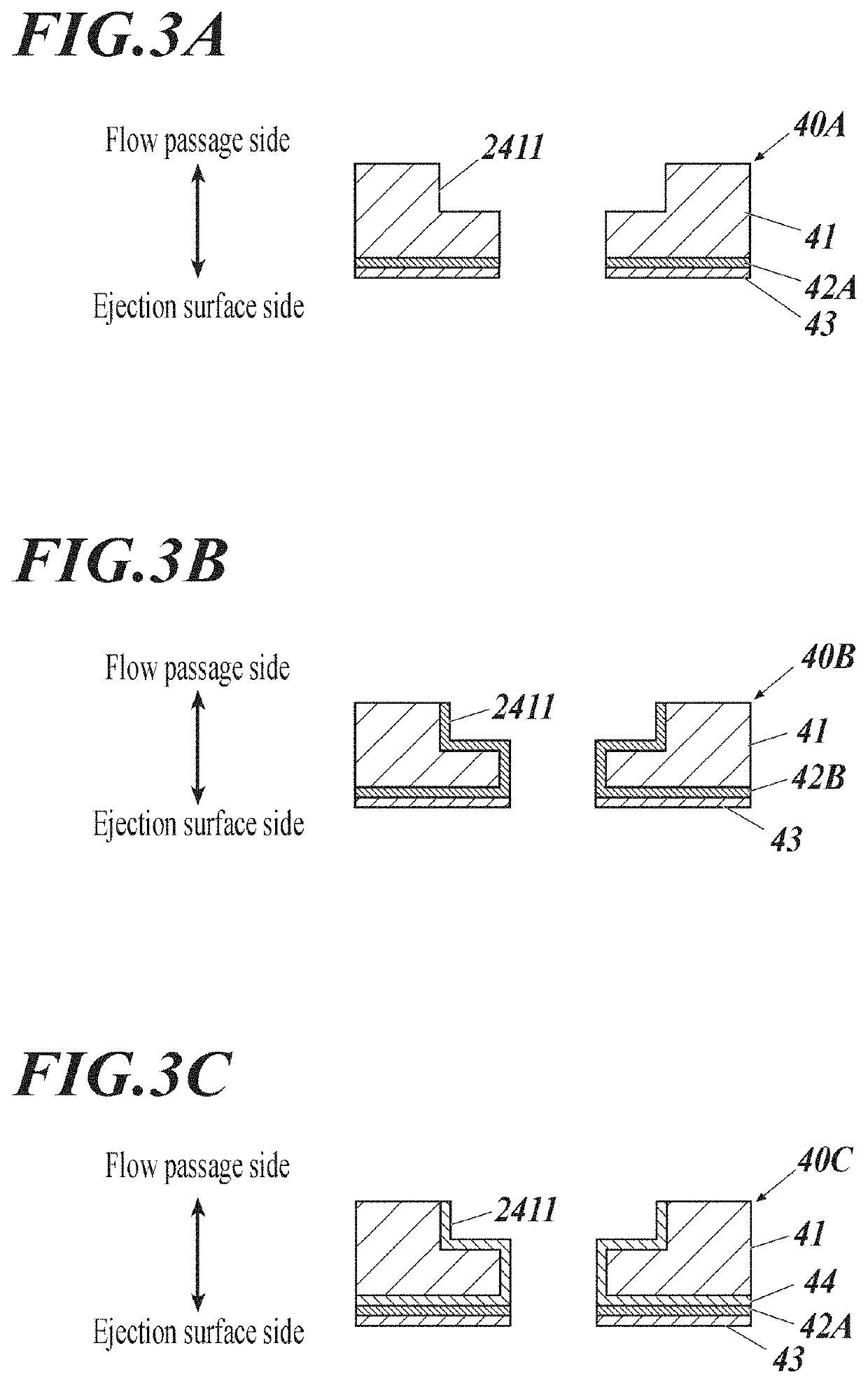
[0149]A nozzle plate 1 having the structure shown in FIG. 3A was produced in accordance with the process described below.

(1) Preparation of Substrate

[0150]As a substrate, a single crystal silicon substrate having a thickness of 100 μm was prepared.

(2) Formation of Liquid-Repellent Layer Base Film 1

[0151]Next, on a silicon substrate, a material gas containing an alkyl silicon compound (abbreviation: TMS, tetramethylsilane, Si(CH3)4)) for forming the liquid-repellent layer base film 1 and argon as a carrier gas were used. A plasma CVD apparatus (plasma CVD apparatus PD-200ST manufactured by SAMCO Corpo...


PUM

PropertyMeasurementUnit
binding energyaaaaaaaaaa
thicknessaaaaaaaaaa

Abstract

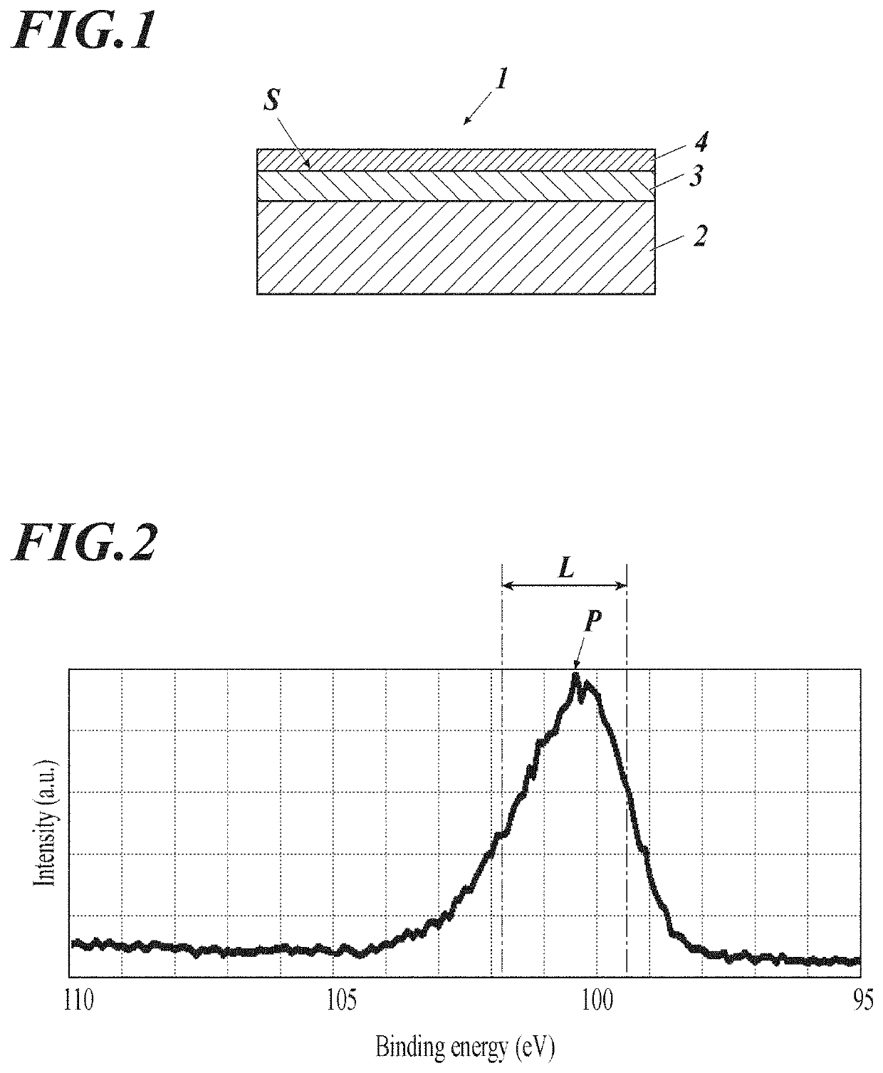
Provided is an inkjet head containing a nozzle plate having at least a substrate, wherein the nozzle plate has a liquid-repellent layer on an outermost surface of the substrate on an ink ejection surface side; a liquid-repellent layer base film is provided between the substrate and the liquid-repellent layer; and the liquid-repellent layer base film contains at least silicon (Si) and carbon (C), and having a maximum peak P of a binding energy of a Si2p orbital of a surface portion measured by X-ray photoeletron spectroscopy is in the range represented by the following Formula (1), Formula (1): 99.6 (eV)≤P≤101.9 (eV).

Description

TECHNICAL FIELD[0001]The present invention relates to an inkjet head, a method of manufacturing an inkjet head, and an inkjet recording method. Specifically, the present invention relates to an inkjet head having a nozzle plate with excellent ink resistance and adhesion, a method of manufacturing the same, and an inkjet recording method capable of obtaining a high-grade inkjet recording image using the same.BACKGROUND[0002]Conventionally, an inkjet recording method has been proposed in which ink droplets are ejected from a nozzle of an inkjet head to form an inkjet image on a recording medium.[0003]In the inkjet head, when ink droplets are ejected, the ink may adhere to the ejection surface of the nozzle (around the ejection side opening of the nozzle) due to the influence of ink mist generated in the inkjet recording apparatus, or bouncing of the ink from the recording medium. It is known that when the ink adheres to the ejection surface and blocks the vicinity of the ejection port...

Claims


Application Information

Patent Timeline
Patent Type & Authority Applications(United States)
IPC IPC(8): B41J2/14B41J2/16
CPCB41J2/14233B41J2/162B41J2/1606B41J2002/14258B41J2/1642B41J2/1646B41J2202/20B41J2/1628B41J2/1634B41J2/1645
Inventor SATO, YOHEISHIMOMURA, AKIHISAKOZAI, HIROAKI
Owner KONICA MINOLTA INC
Learn More