
A testing device for backflow prevention devices

a backflow prevention and testing device technology, applied in the direction of volume measurement, liquid/fluent solid measurement, volume/mass flow by differential pressure, etc., can solve the problems of contaminating the water supply, high water system demand, water pressure may fail or be reduced,

Pending Publication Date: 2022-04-14
GOULD INSTR PTY LTD
View PDF0 Cites 0 Cited by
  • Summary
  • Abstract
  • Description
  • Claims
  • Application Information

AI Technical Summary

Benefits of technology

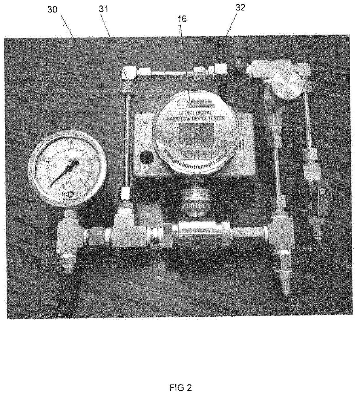
The present invention is a testing device for backflow prevention devices. It solves the problems of conventional mechanical devices by being more accurate, reliable, and longer-lasting. The device uses a digital display, which improves accuracy and eliminates hysteresis. It also includes a transmitting and receiving device, like a wireless access point, to enhance signal transmission. The device measures differential pressure and sends the data electronically to the users' electronic device, eliminating the need for manual recording. The outlet of the device can be connected to the Pitot tube for easy testing. Overall, the invention provides an improved testing experience for backflow prevention devices.

Problems solved by technology

Water pressure may fail or be reduced when a water main bursts, pipes freeze, or there is unexpectedly high demand on the water system (for example, when several fire hydrants are opened).
This reduction in pressure in the pipe may allow water from the soil, from storage, or from other sources to be drawn up into the system, thereby contaminating the water supply.
Conventional devices for testing backflow prevention devices are typically mechanical in nature, making them prone to corrosion and failure.
In addition, mechanical testing devices are, by their very nature, relatively inaccurate, and typically have a margin of error of ±3% of full scale deflection (FSD) of a pressure gauge.

Method used


Image

  • A testing device for backflow prevention devices
  • A testing device for backflow prevention devices
  • A testing device for backflow prevention devices

Examples


Embodiment Construction

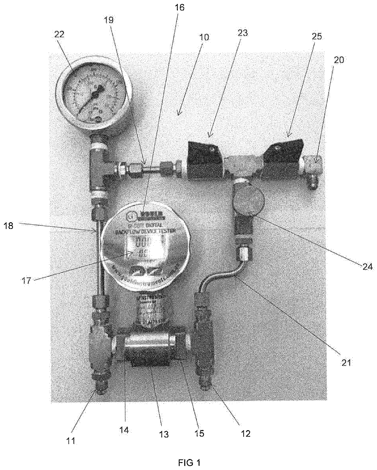
[0097]FIG. 1 illustrates a testing device 10 for a backflow prevention device according to an embodiment of the present invention. The testing device 10 includes a first connection portion 11 adapted for connection to a high pressure side or a low pressure side of a backflow prevention device (not shown) and a second connection portion 12 adapted for connection to the other of the high pressure side or the low pressure side of the backflow prevention device (not shown).

[0098]A portion of the fluid entering the device 10 through the first connection portion 11 and the second connection portion 12 is directed to the measurement portion 13. The measurement portion 13 comprises a conduit in which a differential pressure transducer (obscured) is positioned. Fluid entering the testing device 10 through the first connection portion 11 enters the measurement portion 13 through a first end 14 thereof, while fluid entering the testing device 10 through the second connection portion 12 enters ...


PUM


Abstract

A testing device for backflow prevention devices, the testing device comprising a first connection portion adapted for connection to one of a high pressure side or a low pressure side of a backflow prevention device, a second connection portion adapted for connection to the other of the high pressure side or the low pressure side of the backflow pressure device, and an electronic differential pressure gauge positioned in fluid communication with the first connection portion and the second connection portion and adapted to measure the differential pressure between the high pressure side and the low pressure side of the backflow prevention device.

Description

TECHNICAL FIELD[0001]The present invention relates to a testing device for backflow prevention devices. In particular, the present invention relates to a testing device for measuring the differential pressure in backflow prevention devices.BACKGROUND ART[0002]Backflow prevention devices are typically used to protect water supply systems (and particularly industrial water supply systems) from contamination or pollution due to backflow. In conventional water supply systems, water is maintained at an elevated pressure to enable water to flow from a water outlet. Water pressure may fail or be reduced when a water main bursts, pipes freeze, or there is unexpectedly high demand on the water system (for example, when several fire hydrants are opened). This reduction in pressure in the pipe may allow water from the soil, from storage, or from other sources to be drawn up into the system, thereby contaminating the water supply. Strict safety requirements exist for the dumping of contaminated...

Claims


Application Information

Patent Timeline
Patent Type & Authority Applications(United States)
IPC IPC(8): E03B7/07G01M3/28
CPCE03B7/078G01M3/2876E03B7/077G01F1/46E03C1/10G01F1/34E03B7/07E03C1/104G01F15/005G01F15/066G01F15/006G01F15/185G01F25/10
Inventor GOULD, BRIAN
Owner GOULD INSTR PTY LTD
Learn More