
Method and apparatus for performing container closure integrity testing

a container and integrity testing technology, applied in the direction of measuring devices, structural/machine measurement, instruments, etc., can solve the problems of lack of sensitivity, preventing the exchange of liquid or gas, and subjective testing, so as to reduce the surface tension and high sensitivity of headspace analysis

Active Publication Date: 2022-04-28
LIGHTHOUSE INSTR
View PDF9 Cites 0 Cited by
  • Summary
  • Abstract
  • Description
  • Claims
  • Application Information

AI Technical Summary

Benefits of technology

The present patent combines headspace analysis with a liquid ingress test to identify defects in optically transparent containers. The use of a liquid mitigates the surface tension issues that may arise with pressurized gas ingress tests and simultaneously offers the possibility of dissolving substances that may plug a small defect. The method involves immersing containers in a liquid bath and exposing them to a pressure cycle that forces liquid through the defect using a gas that releases dissolved gas into the container headspace, which is then quantitatively detected using laser spectroscopy. This method overcomes a significant issue in package integrity testing caused by defects masked by the presence of product at the defect location. The patent also provides a method for detecting a defect in a sealed container containing a substance that includes a second liquid and a second gaseous mixture. The presence of the second substance may reduce the detectability of the defect.

Problems solved by technology

Such methods have typically relied on a visual comparison of the color of the liquid product post pressure cycle to standard containers with varying amounts of dye mixed in, leading to a rather subjective test result.
Although these methods are destructive in nature, lack sensitivity and are typically not quantitative, they remain in widespread use.
However, it is not uncommon for substances in the product which the container is designed to contain to block or plug small defects, thereby preventing the exchange of liquid or gas.
The method increases the likelihood of identifying a package defect that may be dogged by product in the defect.

Method used


Image

  • Method and apparatus for performing container closure integrity testing
  • Method and apparatus for performing container closure integrity testing
  • Method and apparatus for performing container closure integrity testing

Examples


Embodiment Construction

[0040]Through one or more of its various aspects, embodiments and / or specific features or sub-components of the present disclosure, are intended to bring out one or more of the advantages as specifically described above and noted below.

[0041]The present disclosure proposes a method for testing the closure integrity of sealed containers. There are only two requirements on the types of containers to be tested: First, at least part of each container is optically transparent and partially filled with gas or at vacuum, thereby allowing the transmission of near-infrared light through the container; and second, each containers is capable of withstanding some amount of overpressure, and in some cases a partial vacuum, on an order of magnitude that is typically experienced during container shipment via air or ground freight.

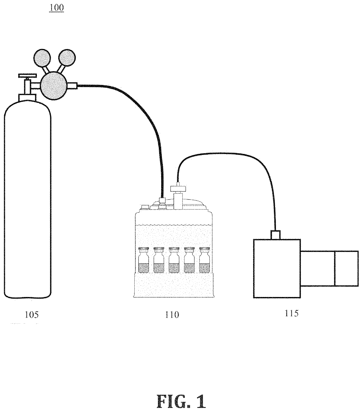
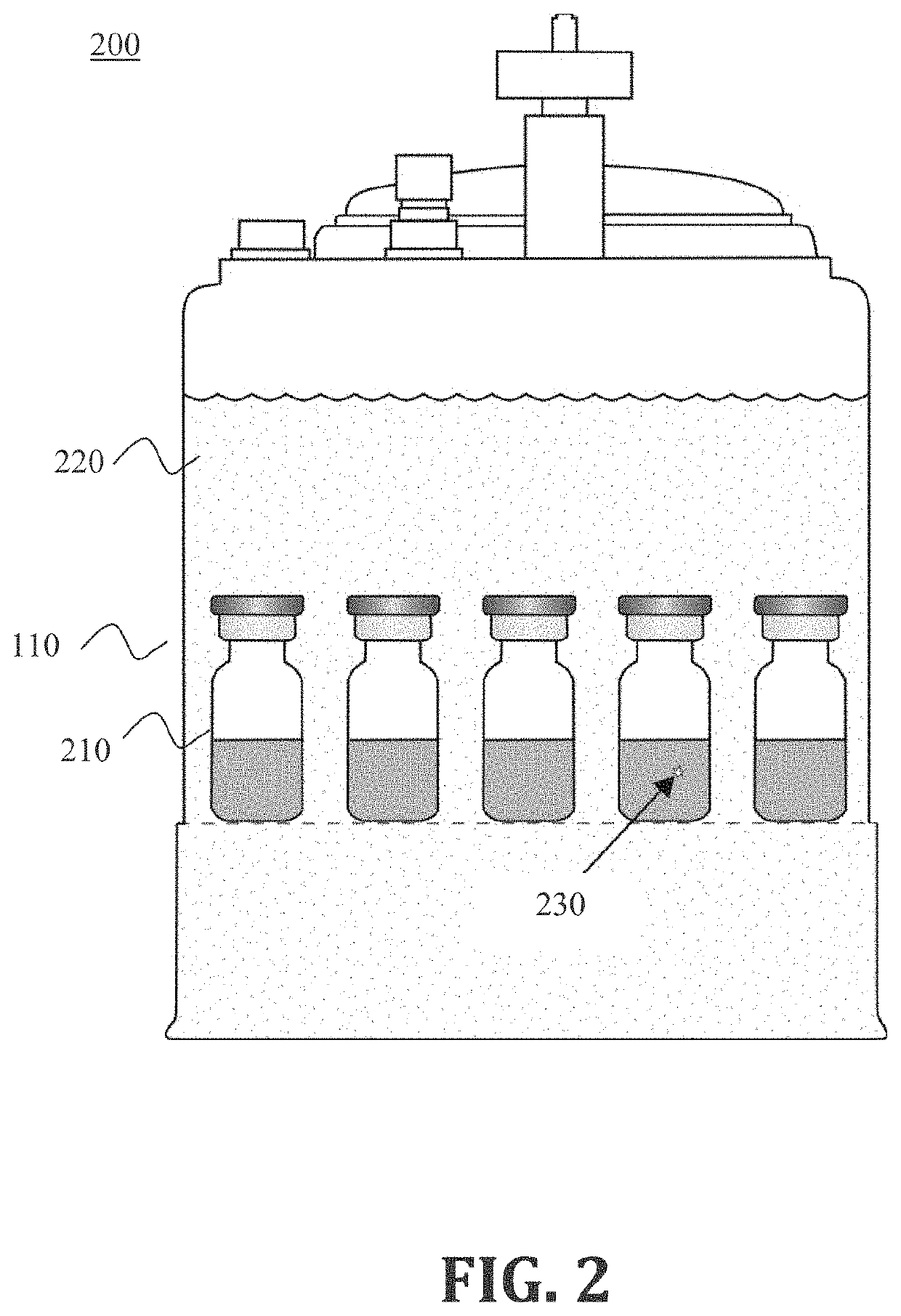
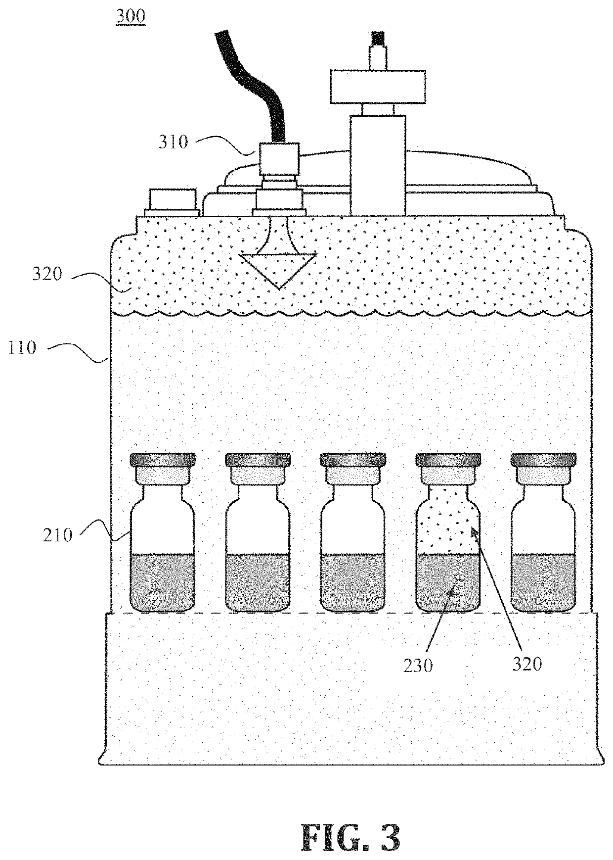
[0042]Referring to FIG. 1, a schematic diagram 100 of components of a leak testing apparatus is illustrated, according to an exemplary embodiment. The components include ...


PUM


Abstract

A method and an apparatus for detecting a defect in a sealed container are provided. The method includes: placing the sealed container in a pressure chamber; filling the chamber with a liquid that is saturated by a test gas such that the sealed container is fully submerged; subjecting the chamber to a pressurized volume of a gaseous mixture that includes the test gas, and then removing the sealed container from the chamber; performing a laser-based headspace analysis of the sealed container in order to measure a partial pressure of the test gas; and using a result thereof to determine whether the sealed container has the defect. The defect may be located on a body of the sealed container that is at or below a level of a product that is contained within the sealed container.

Description

BACKGROUND1. Field of the Disclosure[0001]This technology generally relates to methods and systems for detecting leaks in closed containers, and more particularly to methods and systems for identifying a defect in optically transparent containers in which the defect may be clogged by the presence of a substance in the defect.BACKGROUND INFORMATION[0002]A common method of leak testing sealed containers is to expose said containers to a pressure cycle and perform a measurement which is sensitive to the ingress or egress of gas or liquid into or out of the container as a result of the pressure cycle. Dye ingress methods rely on external overpressure to force a tracer liquid, such as, for example, methylene blue dye, through a defect into a container. Headspace analysis methods typically use a tunable diode laser to detect a change of the container headspace gas composition due to the ingress or egress of gas into or out of a defect in the container. Gas exchange can occur via effusion ...

Claims


Application Information

Patent Timeline
Patent Type & Authority Applications(United States)
IPC IPC(8): G01M3/32
CPCG01M3/329
Inventor TIMMINS, MICHAEL A.VICTOR, KEN G.
Owner LIGHTHOUSE INSTR
Learn More