Torque transmission device for a motor vehicle

Pending Publication Date: 2022-05-05
VALEO EMBRAYAGES SAS
View PDF9 Cites 0 Cited by
  • Summary
  • Abstract
  • Description
  • Claims
  • Application Information

AI Technical Summary

Benefits of technology

[0031]Each clutch may be actuated by a hydraulic receiver (or piston). Each rotary hydraulic receiver may be equipped with a compensation chamber the purpose of which is to compensate for the hydraulic pressure generated by the centrifugal force on the fluid. Thus, the relationship between the force of actuation of the hydraulic receiver and the operating pressure is no longer modified by the rotational speed of the hydraulic receiver. Through i

Problems solved by technology

The use of a differential has the disadvantage of transferring the same torque, in the same direction, to each wheel.
With the use of a conventional differential, when one of the wheels is resting on a slippery surface (black ice for example), it has a tendency to spin, thus limiting the movement of the vehicle.
The use of su

Method used


Image

  • Torque transmission device for a motor vehicle
  • Torque transmission device for a motor vehicle
  • Torque transmission device for a motor vehicle

Examples


Embodiment Construction

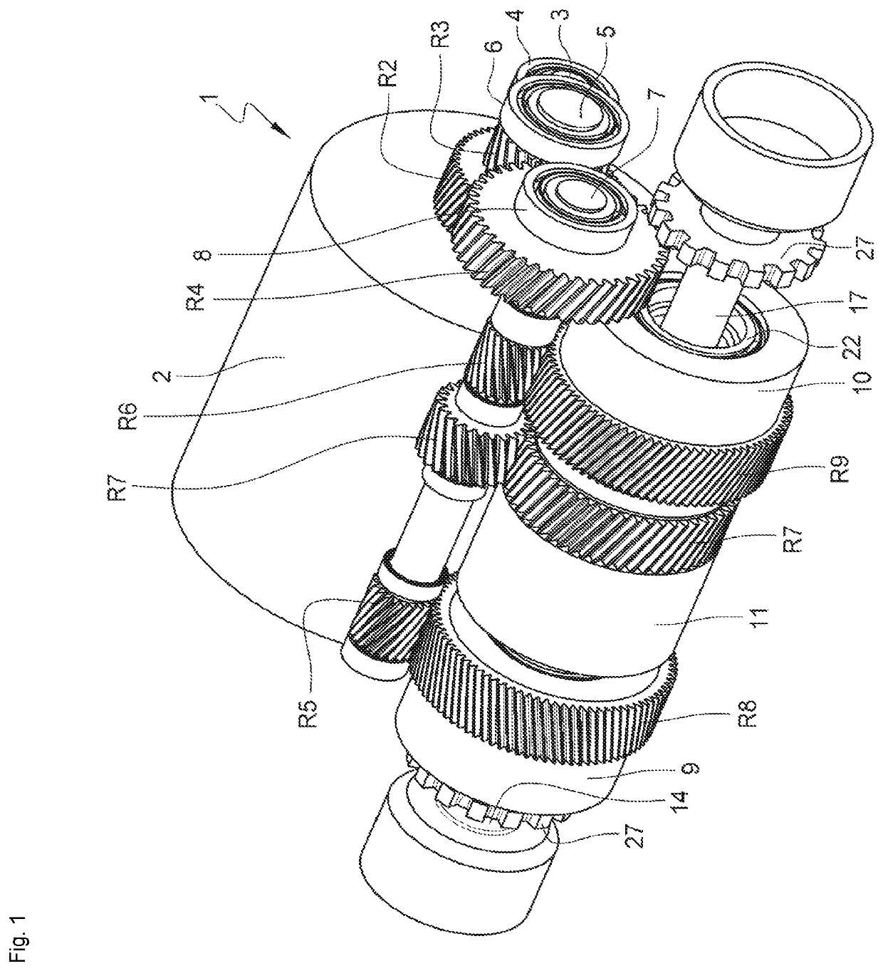
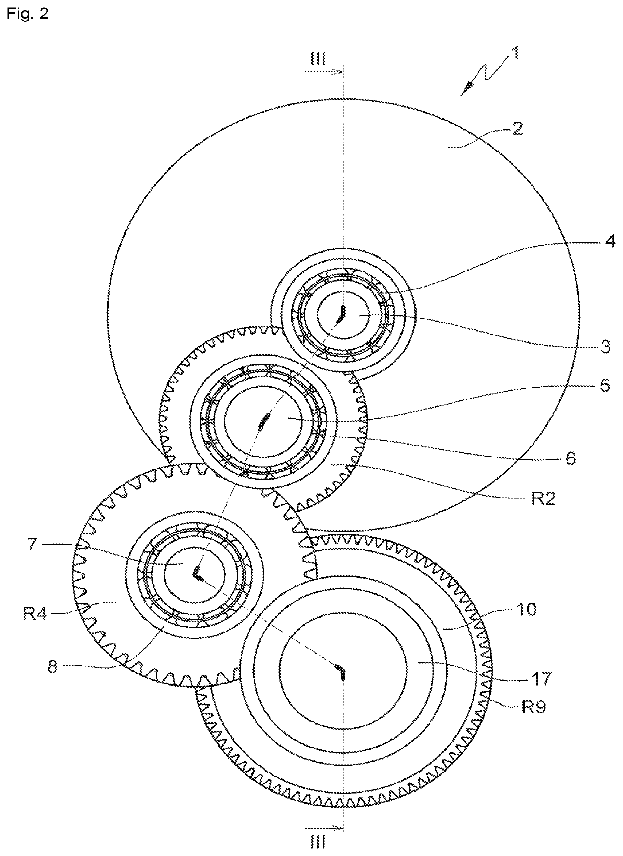
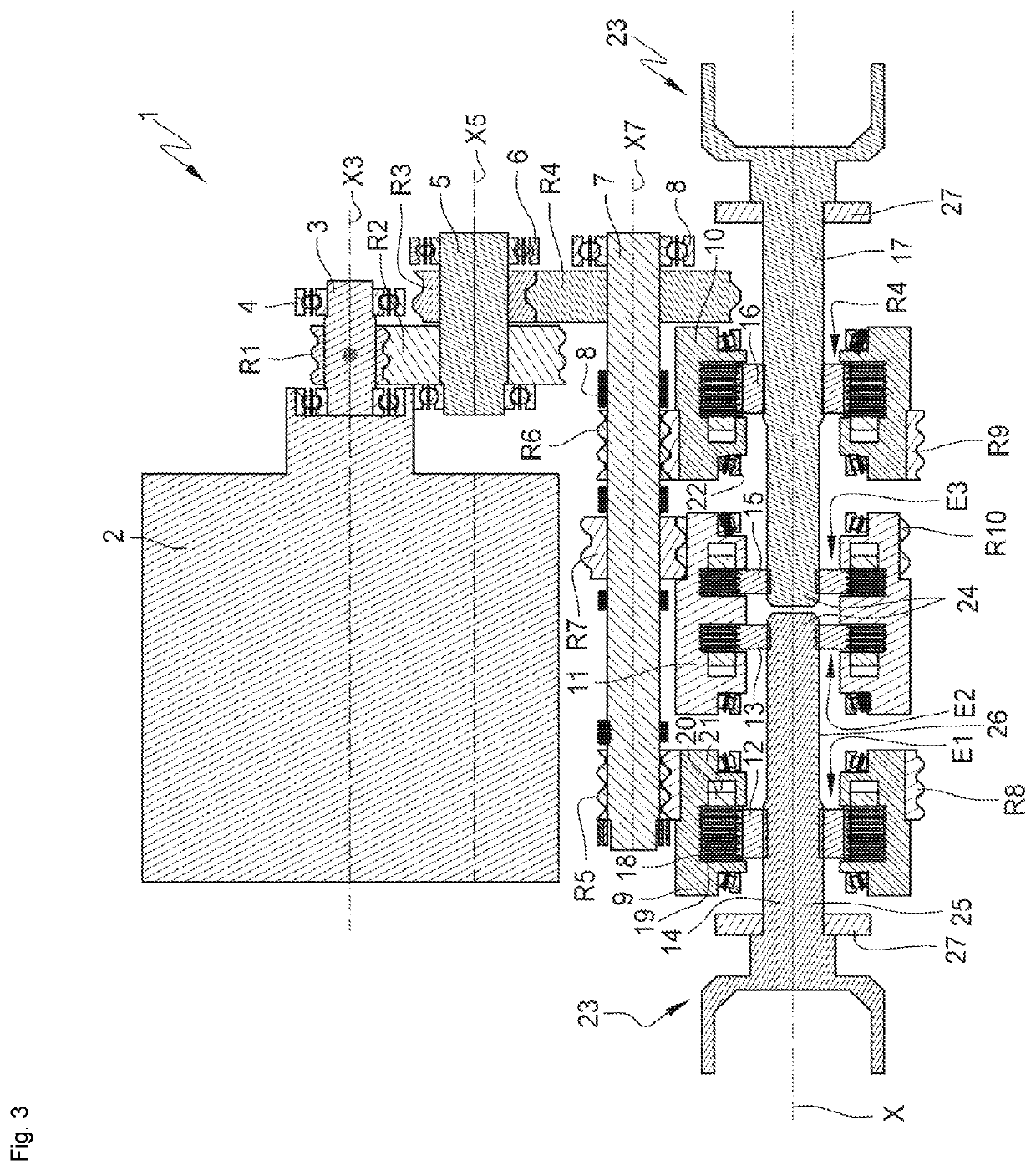
[0120]FIGS. 1 to 3 depict a torque transmission system 1 for a hybrid or fully electric motor vehicle. The transmission system comprises a motor 2 and a transmission device 1 designed to transmit torque between the motor and the wheels of the vehicle.

[0121]The transmission device comprises a first output shaft 14 intended to drive a first wheel of the vehicle, and a second output shaft 17 intended to drive a second wheel of the vehicle, opposite to the first wheel.

[0122]The electric motor 2 comprises a stator, and a rotor coupled to a rotary shaft 3 of the motor 2. The rotary shaft 3 of the motor 2, of axis X3, is guided in rotation via ball bearings 4. The shaft 3 drives a transmission mechanism comprising a gear wheel R1 borne by the shaft 3. The transmission mechanism further comprises a first rotary shaft 5, of axis X5, guided in rotation by ball bearings 6. The first rotary shaft 5 bears a gear wheel R2 and a gear wheel R3. The gear wheel R2 meshes with the gear wheel R1. The d...


PUM


Abstract

A torque transmission device for a motor vehicle includes at least one motor, a first output shaft rotationally coupled to an output element of a first clutch and to an output element of a second clutch, the first output shaft to drive a first wheel of the vehicle, a second output shaft rotationally coupled to an output element of a third clutch and to an output element of a fourth clutch, the second output shaft to drive a second wheel of the vehicle, opposite the first wheel, a torque transfer mechanism to transmit the torque from the motor to an input element of the first clutch and to an input element of the fourth clutch with a first gear ratio, and to transmit the torque from the motor to an input element of the second clutch and to an input element of the third clutch with a second gear ratio.

Description

TECHNICAL FIELD OF THE INVENTION[0001]The invention relates to a torque transmission device for an electric or hybrid vehicle, particularly for an electric or hybrid motor vehicle.PRIOR ART[0002]Motor vehicles may notably belong to one of the following categories:[0003]vehicles propelled by an internal combustion engine,[0004]vehicles known as hybrid vehicles,[0005]vehicles known as electric vehicles.[0006]Vehicles that are propelled by an internal combustion engine conventionally comprise a gearbox and a mechanical or hydraulic transmission system. The role of the gearbox is to adapt the speed and the torque transmitted to the wheels according to the requirements of the user, the speed and the torque of the combustion engine.[0007]Vehicles known as hybrid vehicles generally use an internal combustion engine and an electric motor. Vehicles known as electric vehicles are propelled only using electric motors. The invention applies more particularly to hybrid vehicles and to electric v...

Claims


Application Information

Patent Timeline
IPC IPC(8): F16D25/06F16D48/06
CPCF16D25/06F16D48/06F16D2500/50661F16D2500/1064F16D2500/10412F16D2500/70426F16D2500/1026B60K2001/001B60K17/165B60K17/16B60K17/08F16H1/22B60K2023/043B60K23/04B60K1/00B60K17/043B60K17/02B60Y2200/91B60Y2200/92
Inventor MAUREL, HERVE
Owner VALEO EMBRAYAGES SAS
Why Eureka
Try Eureka