
Power device

a power device and power technology, applied in the direction of electric devices, battery/fuel cell control arrangements, electric devices, etc., can solve the problems of increasing the weight of the automobile, power steering, and load due to temporal consumption of a large curren

Pending Publication Date: 2022-05-12
YAZAKI CORP
View PDF0 Cites 0 Cited by
  • Summary
  • Abstract
  • Description
  • Claims
  • Application Information

AI Technical Summary

Benefits of technology

The present invention aims to extend the life of a capacitor that can handle fluctuations in power and dark current. This is achieved by reducing the internal resistance of the capacitor, which allows it to store electric charges for longer periods of time.

Problems solved by technology

Although the low-voltage system normally consumes a small current, a load (for example, power steering) due to temporal consumption of a large current may be present.
However, mounting such a low-voltage battery on an automobile is costly, resulting in an increase in the weight of the automobile.
However, when electric charges are constantly stored in the capacitor, the internal resistance of the capacitor decreases, so that the life of the capacitor decreases.

Method used


Image

  • Power device
  • Power device
  • Power device

Examples


Embodiment Construction

Power Device 100

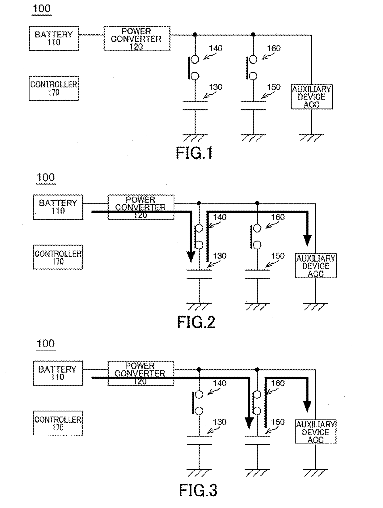
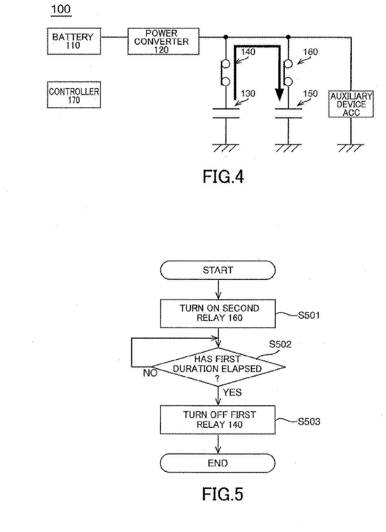
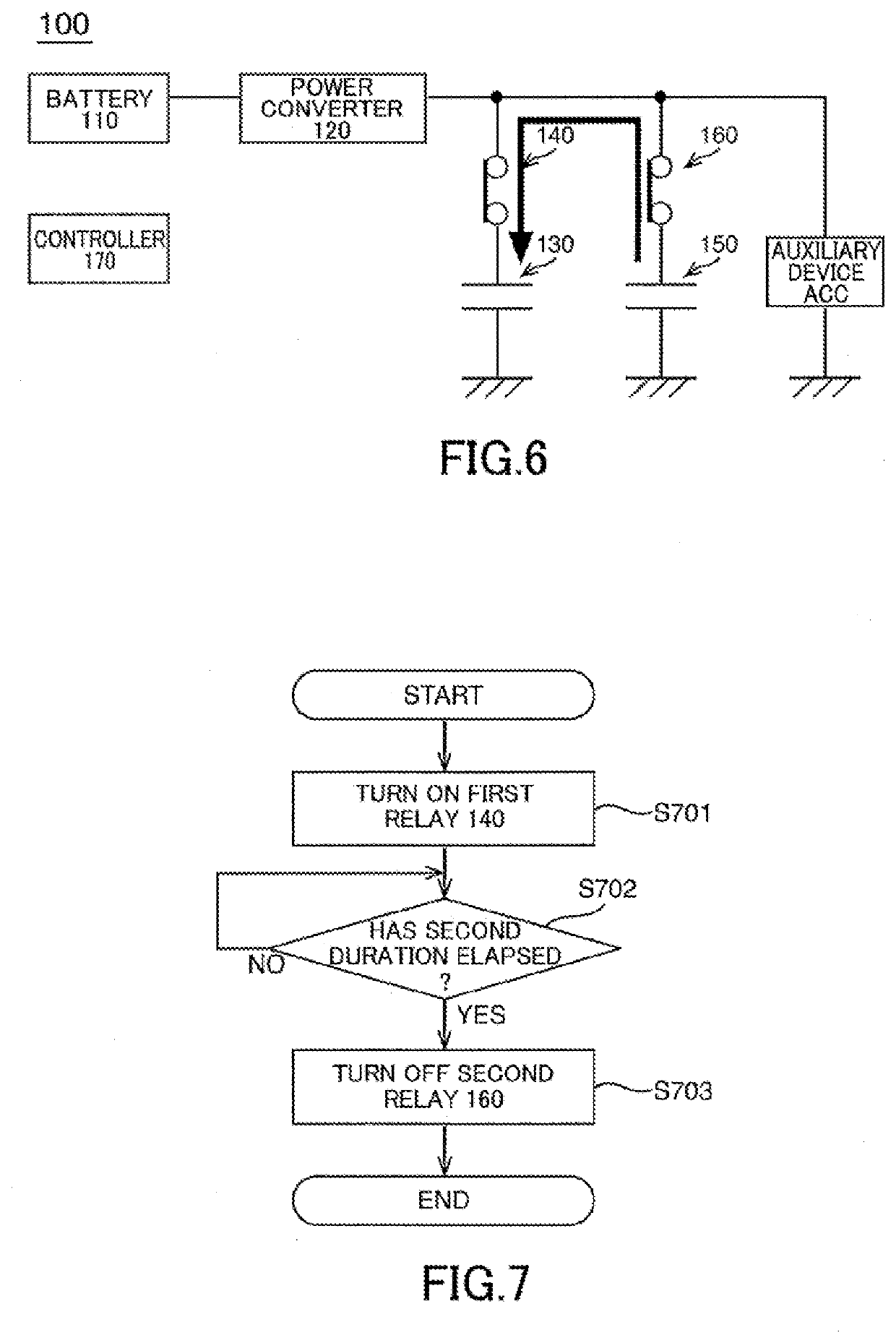
[0022]FIG. 1 illustrates a power device 100 according to an embodiment of the present invention. The power device 100 includes a battery 110, a power converter 120, a first capacitor 130, a first relay 140, a second capacitor 150, a second relay 160, and a controller 170. The power device 100 is mounted on a vehicle such as an automobile.

[0023]The battery 110 supplies power. The battery 110 is, for example, a high-voltage battery that supplies power for traveling of the vehicle.

[0024]The power converter 120 is connected between the battery 110 and an auxiliary device ACC. The power converter 120 is, for example, a DC / DC converter, and the voltage of power output from the battery 110 is converted by the power converter 120 and supplied to the auxiliary device ACC. Although the single auxiliary device ACC is illustrated in FIG. 1, a plurality of auxiliary devices ACC may be provided.

[0025]The first capacitor 130 is connected to a line connecting the power converter 120...


PUM


Abstract

A power device to be mounted on a vehicle is provided. The power device includes a battery, a power converter connected between the battery and an auxiliary device, a first capacitor, a first relay connected between the first capacitor and a line connecting the power converter and the auxiliary device, a second capacitor, a second relay connected between the second capacitor and the line connecting the power converter and the auxiliary device, and a controller configured to control the first relay and the second relay, in which the controller turns on the first relay and turns off the second relay when a power switch of the vehicle is ON, and turns off the first relay and turns on the second relay when the power switch of the vehicle is OFF.

Description

BACKGROUNDTechnical Field[0001]The present invention relates to a power device.Related Art[0002]In a power device mounted on a hybrid vehicle or an electric vehicle, a DC / DC converter is disposed between a high-voltage system in which a high-voltage battery that supplies power for traveling is disposed and a low-voltage system in which an auxiliary device that operates at a low voltage is disposed. In such a power device, the DC / DC converter steps down power output from the high-voltage battery, so that power can be supplied from the high-voltage battery to the auxiliary device.[0003]Such power devices include a power device with a low-voltage battery disposed in a low-voltage system in addition to a high-voltage battery (for example, JP 2019-161839 A). Although the low-voltage system normally consumes a small current, a load (for example, power steering) due to temporal consumption of a large current may be present. The low-voltage battery can cope with a fluctuation in power that ...

Claims


Application Information

Patent Timeline
Patent Type & Authority Applications(United States)
IPC IPC(8): B60L3/00B60L58/10
CPCB60L3/0046B60L58/10H02J7/345H02J7/342B60L1/00B60L1/003B60L50/60B60L58/18B60L2260/162Y02T10/70
Inventor KOMINATO, YASUHIROOKUDA, SADAHARU
Owner YAZAKI CORP
Learn More