Cold spray reinforced impeller shroud

Pending Publication Date: 2022-05-26
NUOVO PIGNONE TECH SRL
View PDF10 Cites 0 Cited by
  • Summary
  • Abstract
  • Description
  • Claims
  • Application Information

AI Technical Summary

Benefits of technology

[0014]The method described herein employs known techniques of additive manufacturing and, in particular, cold spray additive manufacturing to add one or more layers of appropriate materials on the impeller hub and/or on the impeller shroud. The cold spray process is a solid-state coating deposition technology that has recently established as an additive manufacturing process. In comparison with high-temperature additive manufacturing processes, cold spra

Problems solved by technology

However, the centrifugal compressors employing open impellers may exhibit decreased performance and/or efficiencies, for example due to the fact that a portion of the process fluid may flow or leak out of the open impellers through clearances defined between the blades and the statoric part of the compressor, thereby reducing the overall efficiency thereof.
On the other hand, in order to limit the leakage between the impeller blades and the statoric part of the compressor, the clearance in between these components is kept very tight, thus limiting this kind of centrifugal compressors to applications where the relative movement between the impeller blades and the statoric parts of the compressor is not too high.
However, shrouded impe

Method used


Image

  • Cold spray reinforced impeller shroud
  • Cold spray reinforced impeller shroud
  • Cold spray reinforced impeller shroud

Examples


Embodiment Construction

[0033]Certain exemplary embodiments will now be described to provide an overall understanding of the principles of the structure, function, manufacture, and use of the devices, systems, and methods disclosed herein.

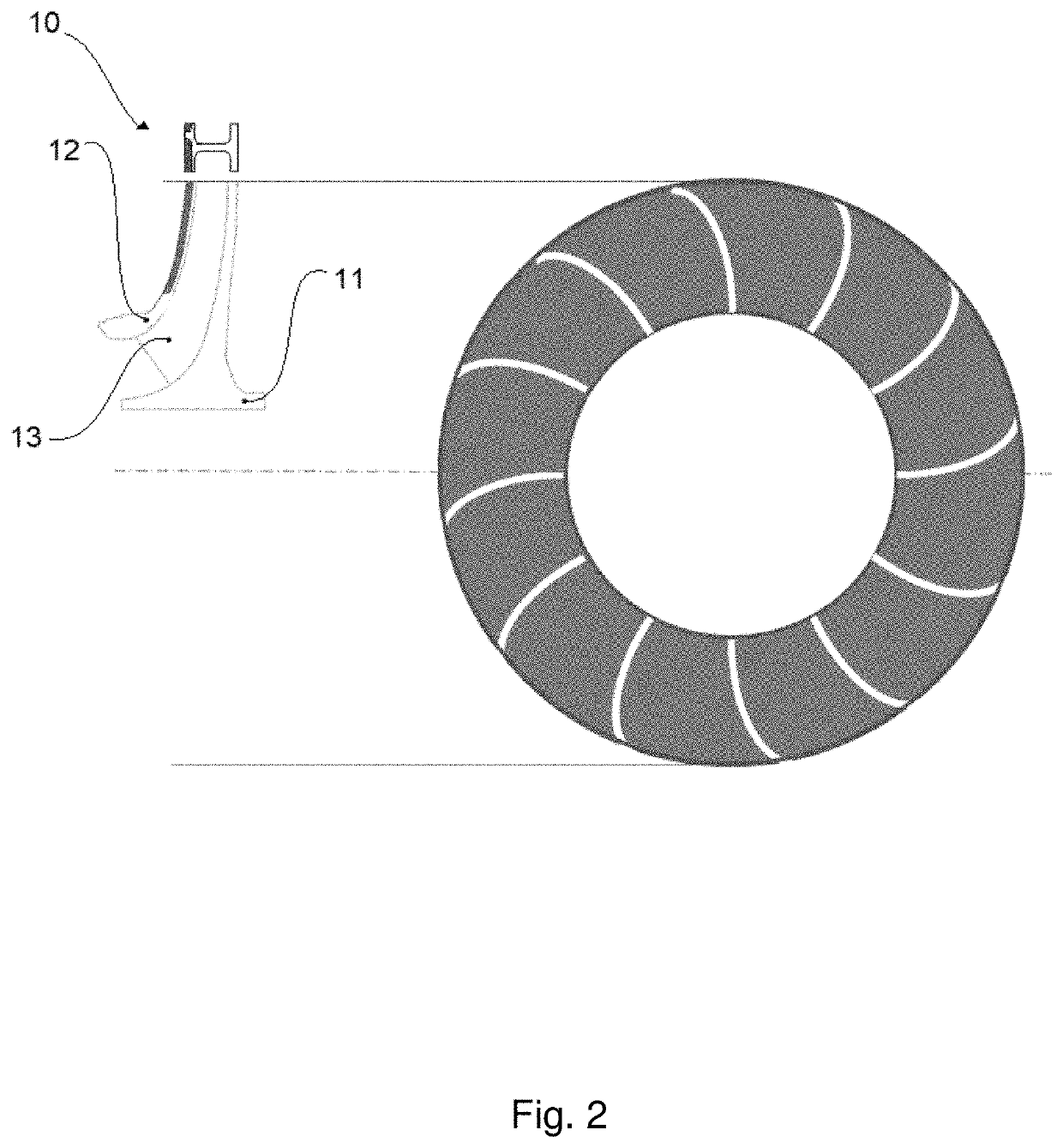
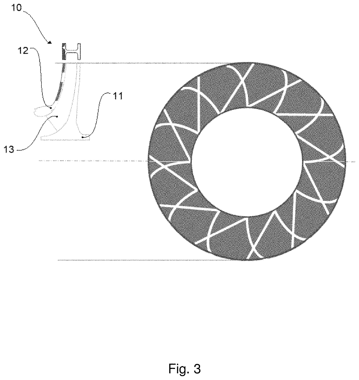
[0034]Centrifugal compressors are a class of turbo machines—or turbo rotating machines—adapted to accelerate the particles of an input compressible fluid, e.g., a gas, through the use of mechanical energy to increase the pressure thereof. Centrifugal compressors exploit centrifugal acceleration to accelerate the input gas particles, e.g., by rotating a centrifugal impeller through which the gas is forced to flow.

[0035]Centrifugal compressors may employ closed or open impellers, that is impellers manufactured with or without a shroud. Shrouded impellers guarantee higher efficiency but have a lower maximum allowable peripheral speed and, consequently, a lower maximum head to provide to the processed fluid. These limitations are due to the fact that the outer periphery of th...


PUM

PropertyMeasurementUnit
Structureaaaaaaaaaa
Densityaaaaaaaaaa
Molecular weightaaaaaaaaaa

Abstract

A shrouded impeller for centrifugal compressors, and methods for manufacturing shrouded impellers for centrifugal compressors are provided. In one embodiment, the method includes manufacturing an impeller base, then depositing by cold spraying at least one layer of metallic material on the surface of the frontal part of the impeller corresponding to the shroud of the impeller and machining the impeller to complete and finish the structure thereof. The at least one layer deposited by cold spraying may include grooves adapted to optimize the dynamic behavior of the impeller by modifying and tuning the local natural frequencies.

Description

CROSS-REFERENCE TO RELATED APPLICATIONS[0001]The present application claims priority to European Application No. 202009619.4 filed on Nov. 24, 2020, which is hereby incorporated herein in its entirety.BACKGROUND[0002]The subject matter of the present disclosure relates to a shrouded impeller and to a method for manufacturing shrouded impellers, in particular for centrifugal compressors, characterized by a reduced mechanical stress caused by the applied centrifugal forces during operation, and adapted to perform at higher peripheral speed with respect to the state-of-the-art technology, without incurring in structural problems.[0003]Radial flow turbo machinery devices are adapted to convert shaft power to kinetic energy (and vice versa) by accelerating (or decelerating) a fluid in a revolving device called impeller. When used as power-absorbing machines, impellers are commonly used to raise the pressure of a fluid or induce a fluid flow in a piping system.[0004]The impeller is the de...

Claims


Application Information

Patent Timeline
IPC IPC(8): F04D29/28F01D5/02C23C24/04
CPCF04D29/284F01D5/02F05D2300/174F05D2230/31C23C24/04F04D29/023F05D2300/173F05D2250/294
Inventor BROGELLI, RICCARDOBELLACCI, MICHELANGELO
Owner NUOVO PIGNONE TECH SRL
Why Eureka
Try Eureka