
Clutch system with phase changing materials

Pending Publication Date: 2022-06-09
THE JOHN HOPKINS UNIV SCHOOL OF MEDICINE
View PDF11 Cites 0 Cited by
  • Summary
  • Abstract
  • Description
  • Claims
  • Application Information

AI Technical Summary

Benefits of technology

The method described in this patent allows for the creation of a heating element that can change between a soft state and a rigid state. This transformation can be controlled by adjusting the voltage applied to the heating element. Additionally, the method results in a resistance to movement of the outer unit relative to the inner unit.

Problems solved by technology

Existing clutch systems can pose a problem for certain applications.
The clutch systems may require large amounts of power to operate, which limits battery life.
The clutch systems also may be too large for certain applications.

Method used


Image

  • Clutch system with phase changing materials
  • Clutch system with phase changing materials
  • Clutch system with phase changing materials

Examples


Embodiment Construction

[0028]Although claimed subject matter will be described in terms of certain embodiments, other embodiments, including embodiments that do not provide all of the benefits and features set forth herein, are also within the scope of this disclosure. Various structural, logical, process step, and electronic changes may be made without departing from the scope of the disclosure. Accordingly, the scope of the disclosure is defined only by reference to the appended claims.

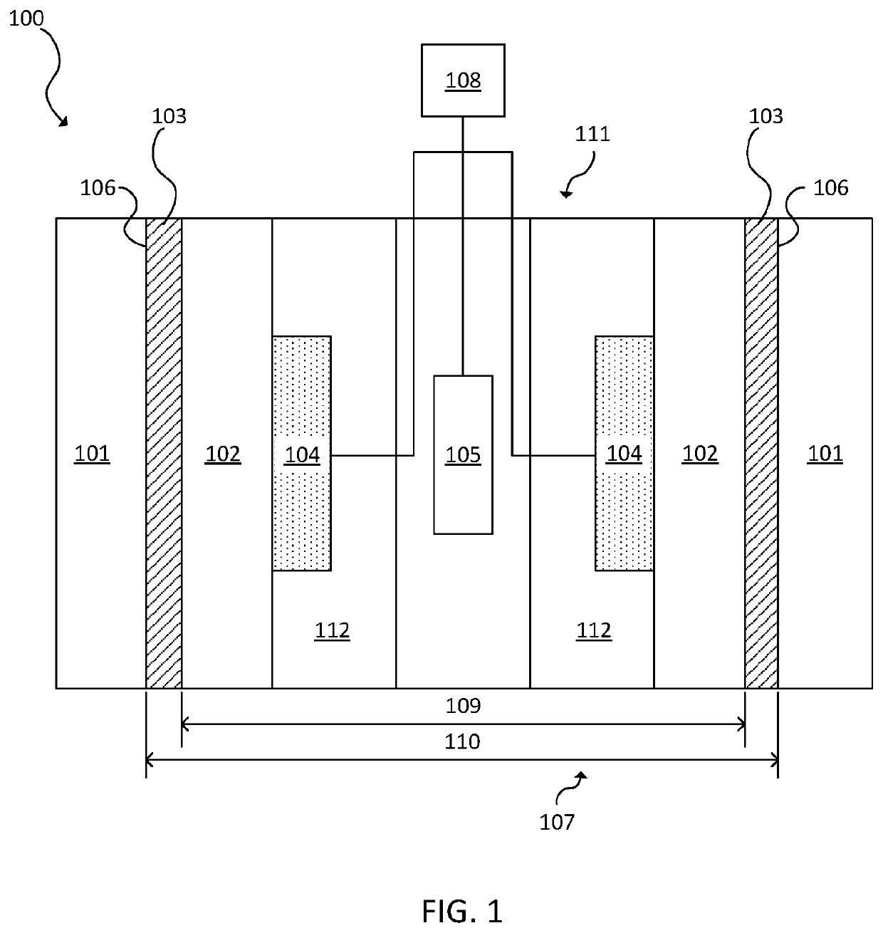
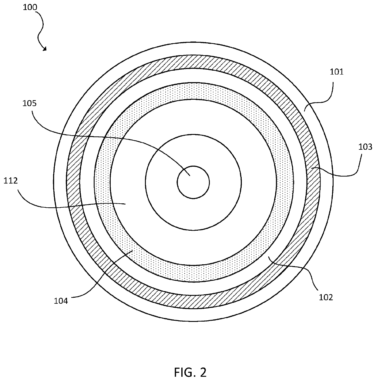
[0029]Embodiments of the clutch system disclosed herein provide locking and unlocking through stiffness tuning of a low melting point (LMP) material as the LMP material changes between solid phase and liquid phase. Thus, the LMP material can be used as a temporary glue or welding. The clutch system may include concentric circular cylinders separated by an LMP material or other surfaces sliding or moving against each other. In the soft state of the LMP material, the clutch is “unlocked” allowing for relative movement of th...


PUM


Abstract

A clutch system is provided. The clutch system includes an outer unit having a surface defining an aperture in the outer unit; an inner unit disposed in the aperture, wherein a shape of the inner unit matches a shape of the aperture; a low melting point material disposed in the aperture between the inner unit and the surface of the outer unit; a heating element; a temperature sensor; and a processor in electronic communication with the heating element and the temperature sensor. The processor is configured to control the heating element thereby changing the low melting point material between a soft state and a rigid state.

Description

CROSS-REFERENCE TO RELATED APPLICATIONS[0001]This application claims priority to U.S. provisional patent application No. 62 / 833,720, filed Apr. 14, 2019, the entire disclosure of which is incorporated herein by reference.FIELD OF THE DISCLOSURE[0002]This disclosure relates to clutch systems.BACKGROUND OF THE DISCLOSURE[0003]Clutches can engage and disengage power transmission, such as between a driving member and a driven member. One shaft is typically attached to an engine or other power unit (the driving member) while the other shaft (the driven member) provides output power for work. Rotational or linear motion can be transferred using the clutch.[0004]Existing clutch systems can pose a problem for certain applications. The clutch systems may require large amounts of power to operate, which limits battery life. The clutch systems also may be too large for certain applications. Therefore, what is needed is an improved clutch system.BRIEF SUMMARY OF THE DISCLOSURE[0005]A clutch sys...

Claims


Application Information

Patent Timeline
IPC IPC(8): F16D37/00F16D21/08
CPCF16D37/008F16D21/08B25J9/104F16D2300/18F16D2200/0034F16D2300/04F16D35/00F16C1/04F16D37/02B25J15/0009B25J15/0233B25J19/0004
Inventor COHEN, ALEXANDERALAMBEIGI, FARSHIDARMAND, MEHRAN
Owner THE JOHN HOPKINS UNIV SCHOOL OF MEDICINE
Learn More