Thermal insulation material for battery pack and battery pack

a technology of thermal insulation material and battery pack, which is applied in the field of thermal insulation materials, can solve the problems of thermal insulation material not being able to retain its shape, gas production or cracking may occur, and urethane binder that is an organic component may be decomposed and deteriorated, so as to achieve the desired thermal insulation properties, reduce the shedding of porous structure, and not easily crushed

Pending Publication Date: 2022-06-09
SUMITOMO RIKO CO LTD +1
View PDF0 Cites 2 Cited by
  • Summary
  • Abstract
  • Description
  • Claims
  • Application Information

AI Technical Summary

Benefits of technology

[0016](1) According to the thermal insulation material for a battery pack of the present invention (hereinafter sometimes simply referred to as the “thermal insulation material of the present invention”), the thermal insulation layer containing the porous structure is sandwiched between the two base materials. This configuration reduces shedding (dusting) of the porous structure. When the compression test is performed in which the thermal insulation material of the present invention is compressed under a load of 15 MPa in the thickness direction, the rate of change of the thickness of the thermal insulation material after the compression test relative to the thickness before the compression test is less than 70%. That is, the thermal insulation material of the present invention is not easily crushed and can maintain desired thermal insulation properties even when compressed.
[0017]In the porous structure forming the thermal insulation layer, the particles are connected to form a skeleton. The porous structure has pores inside and has hydrophobic sites at least on the surface of the porous structure out of the surface and inside of the porous structure. The size of the pores formed between the skeletons of the porous structure is about 10 nm to 50 nm, and most of the pores are so-called mesopores with a size of 50 nm or less. Since the mesopores are smaller than the mean free path of air, heat transfer is impeded. Therefore, the thermal insulation material of the present invention having the thermal insulation layer has a good thermal insulation effect.
[0018]The thermal insulation layer contains the metal oxide nanoparticles as a binder that binds constituent components. Since no organic material is used as a binder, neither gas is produced nor cracking occurs due to decomposition and deterioration of the binder even when used in a high temperature atmosphere. Accordingly, the thermal insulation layer can retain its shape even at high temperatures, and its mass is less likely to decrease. That is, when the thermal insulation layer is held at 500° C. for 30 minutes, the percentage mass loss of the thermal insulation layer calculated from the mass before and after that is 10% or less.
[0019]The thermal insulation layer is harder when using the metal oxide nanoparticles as a binder than when using an organic material such as urethane resin as a binder. Therefore, the thermal insulation layer is not easily crushed and can maintain its thermal insulation structure even when compressed. Since the nanoparticles (particles on the order of nanometers) are used as a binder instead of the bulk crystals described in Patent Document 6, the disadvantage of using an inorganic compound as a binder, namely the disadvantage that the thermal insulation layer becomes hard and brittle, is reduced.
[0020]Moreover, the thermal insulation layer contains the reinforcing fibers. Due to the actions of both the metal oxide nanoparticles and the reinforcing fibers, the thermal insulation layer has improved shape retention at high temperatures (heat resistance) and is neither easily crushed nor broken even when compressed (that is, has improved compression resistance). The thermal insulation layer can thus maintain its thermal insulation properties even when compressed. Since the thermal insulation layer contains the reinforcing fibers, the stability and film forming properties of a coating material for forming the thermal insulation layer are improved. As a result, the strength and heat resistance of the thermal insulation layer are improved. The thermal insulation material for a battery pack of the present invention thus has good thermal insulation properties, heat resistance, and compression resistance.
[0021](2) According to the battery pack of the present invention, the thermal insulation material of the present invention is interposed between adjacent ones of the battery cells. As described above, the thermal insulation material of the present invention is not easily crushed even when compressed. Therefore, according to the battery pack of the present invention, the thermal insulation properties of the thermal insulation material are less likely to be reduced even when the battery cells are pressed from both sides in the stacking direction. The thermal insulation layer forming the thermal insulation material of the present invention has not only good thermal insulation properties but also good shape retention at high temperatures (heat resistance). Moreover, the thermal insulation layer is neither easily crushed nor broken even when compressed (that is, the thermal insulation layer has good compression resistance). According to the battery pack of the present invention, even if the temperature of one battery cell rises, heat transfer between this battery cell and its adjacent battery cell is reduced due to the thermal insulation material of the present invention interposed between these battery cells. A chain reaction of temperature rise is therefore reduced.

Problems solved by technology

However, when a conventional thermal insulation material using a urethane binder is used in a high temperature atmosphere of about 500° C., the urethane binder that is an organic component may be decomposed and deteriorated.
As a result, gas may be produced or cracking may occur, and the thermal insulation material may not be able to retain its shape.
Moreover, since the urethane binder is relatively soft, the thermal insulation material is crushed when compressed and it is difficult for the thermal insulation material to maintain its thermal insulation structure.

Method used


Image

  • Thermal insulation material for battery pack and battery pack
  • Thermal insulation material for battery pack and battery pack

Examples


first embodiment

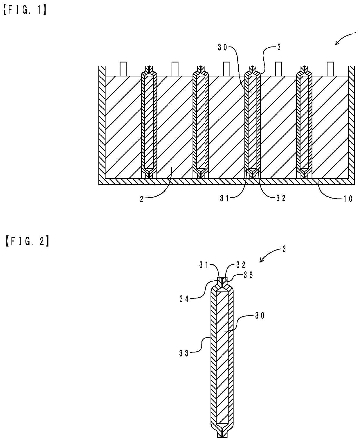
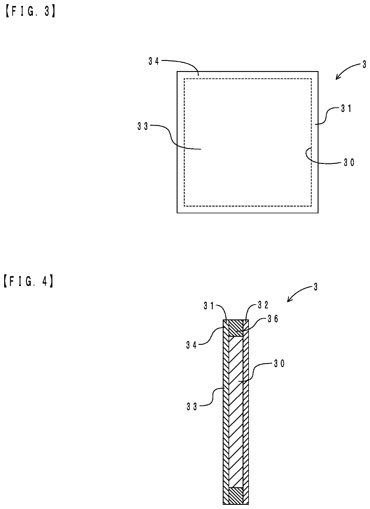
[0027]First, the configuration of a thermal insulation material for a battery pack (hereinafter sometimes simply referred to as the “thermal insulation material” in the description of the embodiment) and a battery pack of a first embodiment will be described. FIG. 1 is a schematic sectional view illustrating the configuration of the battery pack of the present embodiment. FIG. 2 is a sectional view of the thermal insulation material housed in the battery pack. FIG. 3 is a front view of the thermal insulation material. In FIG. 3, a thermal insulation layer is shown as seen through by dashed line for convenience of explanation. As shown in FIGS. 1 and 2, a battery pack 1 has a housing 10, a plurality of battery cells 2, and a thermal insulation material 3.

[0028]The housing 10 is made of metal and has a box shape. The battery cells 2 are lithium ion batteries. Each battery cell 2 is in the shape of a rectangular thin plate, and the battery cells 2 are stacked in the thickness direction...

second embodiment

[0038]A thermal insulation material and a battery pack of the present embodiment are different from those of the first embodiment in that a fixing member rather than the fused portion is placed in the peripheral edge portion of the thermal insulation material. The following description focuses on the difference. FIG. 4 is a sectional view of the thermal insulation material of the present embodiment. FIG. 4 corresponds to FIG. 2, and the same portions as those in FIG. 2 are denoted by the same signs as those in FIG. 2.

[0039]As shown in FIG. 4, the thermal insulation material 3 has the thermal insulation layer 30, the first base material 31, and the second base material 32. The thermal insulation layer 30 is sandwiched between the first base material 31 and the second base material 32 that are made of a glass cloth. The thermal insulation material 3 has the body portion 33 and the peripheral edge portion 34. A fixing member 36 is placed in the peripheral edge portion 34, that is, betw...

examples

[0069]Next, the present invention will be described in more detail using examples.

[0070](1) Manufacturing of Thermal Insulation Material for Battery Pack

[0071]First, various coating materials for a thermal insulation layer were prepared according to the amounts (unit: parts by mass) shown in Tables 1 and 2 below. Next, the surface of a first glass cloth is coated with each of the prepared coating materials for a thermal insulation layer with a thickness of 2 mm. Then, a second glass cloth was placed on the coating film to form a laminate. The laminate was placed in a hot air oven and held at 80° C. for 1 hour, and then heated to 100° C. and dried until the mass no longer decreased. A sheet-like thermal insulation material sample composed of the first glass cloth, the thermal insulation layer, and the second glass cloth was thus manufactured. The first glass cloth is included in the concept of the first base material in the present invention, and the second glass cloth is included in...


PUM

PropertyMeasurementUnit
lengthaaaaaaaaaa
lengthaaaaaaaaaa
lengthaaaaaaaaaa

Abstract

A thermal insulation material for a battery pack includes: a thermal insulation layer; and a first base material and a second base material that are arranged with the thermal insulation layer interposed therebetween. The thermal insulation layer contains a porous structure in which a plurality of particles is connected to form a skeleton, reinforcing fibers, and metal oxide nanoparticles serving as a binder, the porous structure having pores inside and having hydrophobic sites at least on a surface of the porous structure out of the surface and inside of the porous structure, and a percentage mass loss of the thermal insulation layer in thermogravimetric analysis in which the thermal insulation layer is held at 500° C. for 30 minutes is 10% or less.

Description

TECHNICAL FIELD[0001]The present invention relates to a thermal insulation material that is placed between battery cells in a battery pack housing a plurality of battery cells.BACKGROUND ART[0002]Hybrid vehicles and electric vehicles are equipped with a battery pack housing a plurality of battery cells. In the battery pack, a battery module composed of a stack of the battery cells is fixed from both sides in the stacking direction by a tightening member and housed in a housing. For example, Patent Document 1 describes a composite sheet interposed between adjacent battery cells. The composite sheet has a thermal insulation layer. When the temperature of one battery cell rises, the composite sheet reduces heat transfer to battery cells adjacent to this battery cell. The thermal insulation layer is made of a non-woven fabric carrying silica xerogel thereon.[0003]Silica xerogel and silica aerogel are porous materials in which fine silica particles are connected to form a skeleton and wh...

Claims


Application Information

Patent Timeline
Patent Type & Authority Applications(United States)
IPC IPC(8): H01M10/658
CPCH01M10/658H01M50/209H01M50/24H01M50/231H01M50/222H01M10/651F16L59/02Y02E60/10H01M10/0525H01M10/647H01M50/204
Inventor KATAYAMA, NAOKIKUMAGAI, SHINJIHAYASHI, SHOTATAGUCHI, YUTAROSHINTAKU, YUJI
Owner SUMITOMO RIKO CO LTD
Why Eureka
Try Eureka