Ultrasonic tool and ultrasonic connection device herein

a technology of ultrasonic connection and ultrasonic tool, which is applied in the direction of mechanical vibration separation, conductors, non-electric welding apparatuses, etc., can solve the problems of contamination of the connecting component or its environment, difficulty in coupling the laser beam into the longitudinal recess, etc., to improve the degree of absorption, improve the suitability of the ultrasonic tool for laser-supported ultrasonic bonding or laser-supported ultrasonic welding, and prevent the effect of persons

Pending Publication Date: 2022-06-23
HESSE
View PDF0 Cites 0 Cited by
  • Summary
  • Abstract
  • Description
  • Claims
  • Application Information

AI Technical Summary

Benefits of technology

[0008]An advantage of the invention is that the suitability of the ultrasonic tool for laser-supported ultrasonic bonding or laser-supported ultrasonic welding is improved. The surface-structured absorption surface ensures, on the one hand, that a laser beam directed at it can be substantially absorbed, and otherwise diffusely reflected, with the result that a specular reflection is avoided and damage to surrounding components of the ultrasonic connection arrangement such as the optical components of the laser generator forming and / or guiding the laser beam (lenses, optical waveguides or the like), damage to the therefore sensitive connecting components and danger to persons is prevented. On the other hand, the surface-structured absorption surface improves the degree of absorption with the result that a high percentage of the energy supplied via the laser beam heats the ultrasonic tool and only a comparatively small percentage is reflected. In particular, the surface-structured absorption surface can be designed as a beam trap for an incident laser beam in such a way that the laser beam impinging on the absorption surface is reflected several times on the absorption surface and is always absorbed proportionately.
[0009]In addition, it has been shown that the surface is enlarged by the structuring. This causes the radiation intensity or the laser surface power density to decrease. This way, such a degradation or destruction of the ultrasonic tool itself is prevented, as are the loosening of particles and formation of vapors and, ultimately, the contamination of the connecting point. In addition, the absorption surface, since it is formed on the tool cover surface, i.e., on the outside of the ultrasonic tool, can be produced comparatively cost-effectively and with high quality or regularity.
[0010]The end region of the ultrasonic tool can be defined on the one hand by the connecting contact surface. On the other hand, the absorption surface is at least partially and preferably completely located in the end region and the end region has a maximum extension of 15 mm in the longitudinal direction of the tool, starting from the connecting contact surface, wherein the end region covers at most one third of a length of the ultrasonic tool. For very short ultrasonic tools, which are used, for example, in ultrasonic ball bonding, the end region can be shorter than 15 mm. For ultrasonic tools with a length of more than 45 mm, the end region is shorter than one third of the length of the ultrasonic tool.
[0011]The absorption coefficient of the absorption surface can be greater than the absorption coefficient of the tool cover surface outside the end region or as the absorption coefficient of a second partial surface of the tool cover surface in the end region. The first partial surface and the second partial surface can be adjacent to each other or be separated from each other, for example by another partial surface. Advantageously, the absorption capacity of the ultrasonic tool can be further improved and the heating of the ultrasonic tool, preferably adjacent to the connecting contact surface, can be facilitated.
[0012]The absorption surface can be regularly structured. Due to the regular structuring, the absorption capacity is essentially constant across the absorption surface. Temperature peaks are thus avoided, and unacceptably high local heating is prevented. In addition, the ultrasonic tool is easy to manufacture and scattering between the ultrasonic tools is low.
[0013]The ultrasonic tool can taper in the end region. For example, the ultrasonic tool becomes wedge-shaped. In any case, a cross-section established vertically to the longitudinal direction of the tool decreases in sections. Preferably, the outer dimensions of the ultrasonic tool in the direction of the connecting contact surface also continuously decrease.

Problems solved by technology

A disadvantage of the solutions described in the conventional art is that, depending on the structural and spatial conditions, coupling the laser beam into the longitudinal recess and replacing the ultrasonic tool can be difficult.
In addition, when the laser beam impinges on the connecting component, vapors can form or particles can be released, so that contamination of the connecting component or its environment occurs.

Method used


Image

  • Ultrasonic tool and ultrasonic connection device herein
  • Ultrasonic tool and ultrasonic connection device herein
  • Ultrasonic tool and ultrasonic connection device herein

Examples


Embodiment Construction

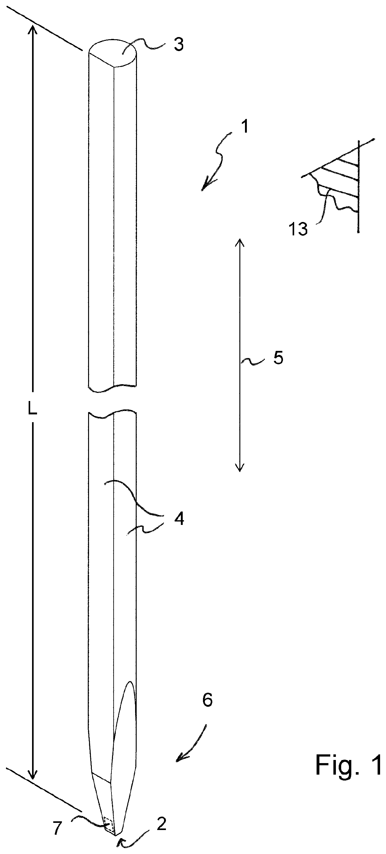
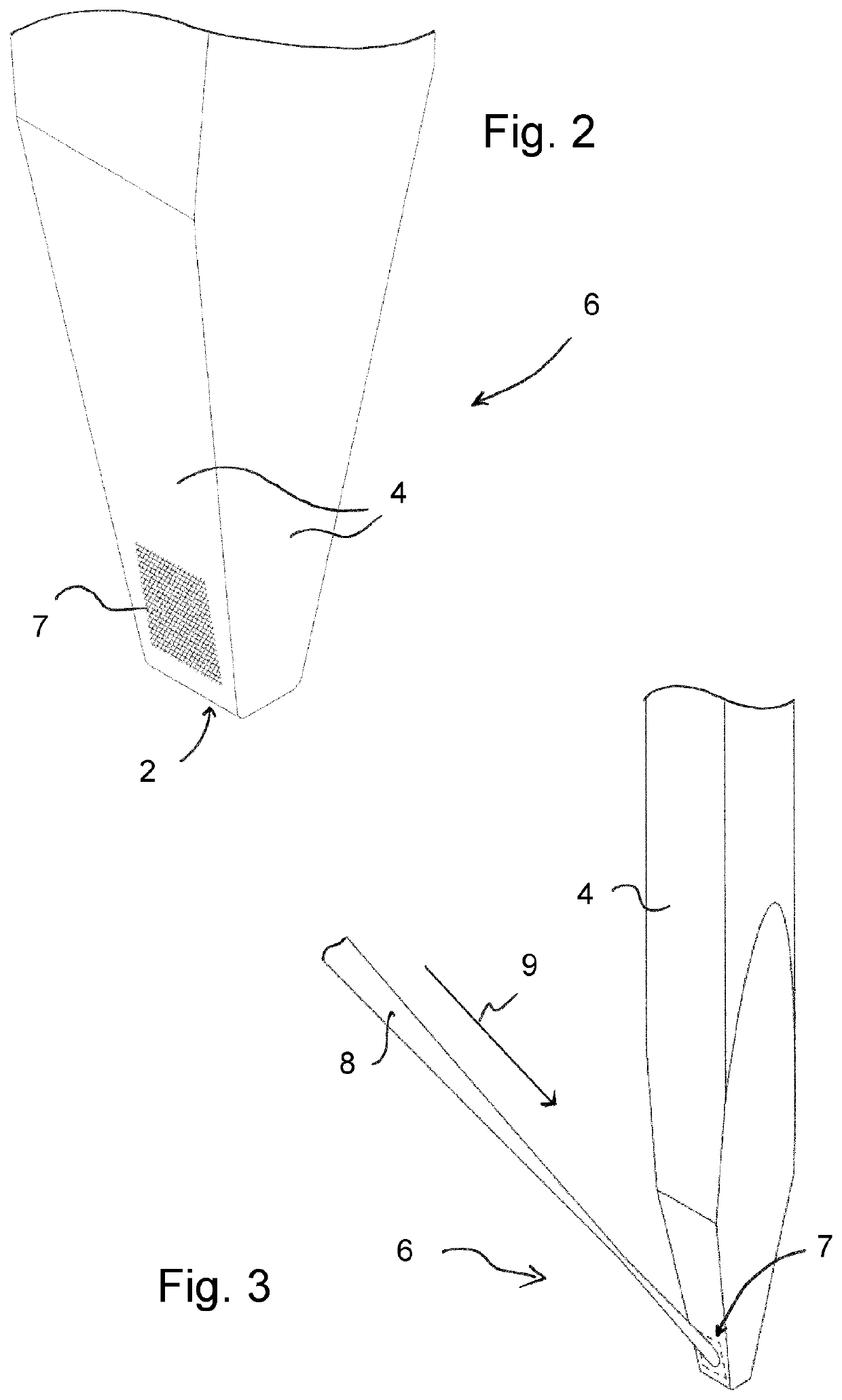
[0049]The ultrasonic tool 1 according to FIG. 1 provides a first end face 2 formed as a connecting contact surface, a second end face 3, which is opposite the first end face 2, and a tool cover surface 4 connecting the end faces 2, 3. The ultrasonic tool 1 is elongated in a longitudinal direction of the tool 5. It has a length L from the first end face 2 to the second end face 3, which is greater than 50 mm. With respect to the longitudinal direction of the tool 5, the lower 15 mm of the ultrasonic tool 1 comprising the connecting contact surface 2 form an end region 6 of the ultrasonic tool 1. In the end region 6, the ultrasonic tool 1 tapers in a wedge-shaped manner in respect of a cross-section oriented vertically to the longitudinal direction of the tool 5 in the direction of the connecting contact surface 2. The ultrasonic tool 1 is symmetrically designed in relation to a longitudinal center plane of the tool 13 which receives the longitudinal direction of the tool 5.

[0050]The ...


PUM


Abstract

An ultrasonic tool comprising a first end face and a second end face, which is opposite the first end face, as well as a tool cover surface connecting the first end face and the second end face, wherein the ultrasonic tool is elongated in a longitudinal direction of the tool, wherein at least the first end face is formed as a connecting contact surface, which is arranged for pressing the ultrasonic tool against a connecting component, and wherein the ultrasonic tool comprises an end region comprising the connecting contact surface, which extends from the connecting contact surface in the longitudinal direction of the tool over 15 mm, but at most extends one third of the length of the ultrasonic tool in the direction of the opposite end face, and wherein in the end region, a first partial surface of the tool cover surface is formed as a surface-structured absorption surface.

Description

[0001]This nonprovisional application is a continuation of International Application No. PCT / DE2020 / 100794, which was filed on Sep. 11, 2020, and which claims priority to German Patent Application No. 10 2019 124 332.7, which was filed in Germany on Sep. 11, 2019, and German Patent Application No. 10 2019 124 333.5, which was filed in Germany on Sep. 11, 2019, and German Patent Application No. 10 2019 124 334.3, which was filed in Germany on Sep. 11, 2019, and German Patent Application No. 10 2019 124 335.1, which was filed in Germany on Sep. 11, 2019, and which are all herein incorporated by reference.BACKGROUND OF THE INVENTIONField of the Invention[0002]The present invention relates to an ultrasonic tool comprising a first end face and a second end face, which is opposite the first end face, as well as a tool cover surface connecting the first end face and the second end face, wherein the ultrasonic tool is elongated in a longitudinal direction of the tool, wherein at least the f...

Claims


Application Information

Patent Timeline
Patent Type & Authority Applications(United States)
IPC IPC(8): B23K20/10B23K20/00B06B1/02
CPCB23K20/106B23K2101/38B06B1/02B23K20/004B06B1/06B06B2201/72B06B2201/55B23K20/10B23K2103/10B23K2103/12B23K20/007
Inventor UNGER, ANDREASBROEKELMANN, MICHAELHUNSTIG, MATTHIASHESSE, HANS-JUERGEN
Owner HESSE
Why Eureka
Try Eureka