Method of manufacturing a hollow spring member

a manufacturing method and hollow spring technology, applied in the direction of shock absorption devices, furnaces, heat treatment devices, etc., can solve the problems of the sealing of the conventional terminal portion,

Active Publication Date: 2022-06-30
NHK SPRING CO LTD
View PDF1 Cites 0 Cited by
  • Summary
  • Abstract
  • Description
  • Claims
  • Application Information

AI Technical Summary

Benefits of technology

[0006]Accordingly, an object of the present invention is to provide a hollow spring member having a terminal sealed portion in which a distal end of a rod is reliably closed.
[0009]According to the hollow spring member of the present invention, a thickness of the distal-end-center closure portion formed at the end wall portion of the terminal sealed portion can be made less than a thickness of a part surrounding the distal-end-center closure portion due to the recess. Accordingly, in regard to a temperature change (heating, quenching, etc.,) which occurs in heat treatment, etc., a part near the distal-end-center closure portion will have a uniform temperature most quickly. Thus, an influence of thermal stress resulting from an excessive temperature difference caused at the distal-end-center closure portion is suppressed, and sealability of the distal-end-center closure portion can be ensured.

Problems solved by technology

As a result of intensive study conducted by the present inventors, it has been found that a conventional terminal sealed portion has a problem.
For example, when heat treatment such as quenching and tempering was performed for the hollow spring member, sealability of the terminal sealed portion had a problem, which is assumed to have resulted from a rapid temperature change of the rod affecting the terminal sealed portion.

Method used


Image

  • Method of manufacturing a hollow spring member
  • Method of manufacturing a hollow spring member
  • Method of manufacturing a hollow spring member

Examples


first embodiment

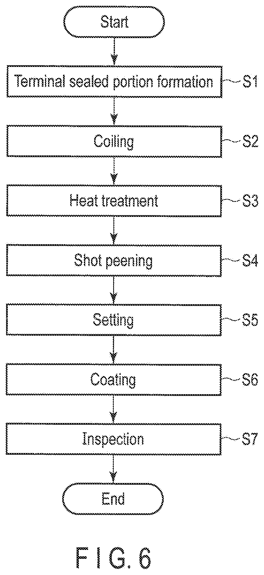
[0024]A hollow coil spring and a method of manufacturing the hollow coil spring will described with reference to FIGS. 1 to 6. The hollow coil spring is an example of a hollow spring member.

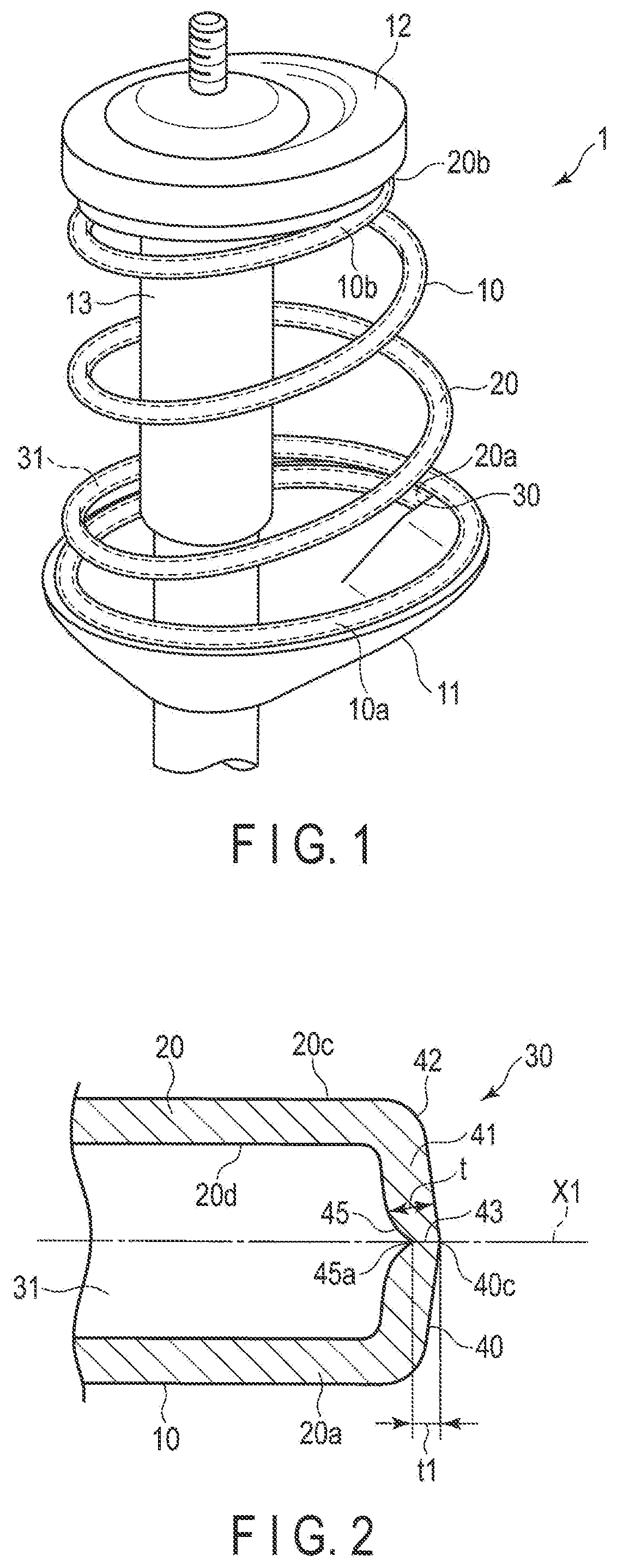
[0025]FIG. 1 shows a part of a McPherson-strut-type suspension 1, as an example of a vehicle suspension. The suspension 1 of the present embodiment comprises a hollow coil spring 10, a lower spring seat 11, an upper spring seat 12, and a shock absorber 13. The lower spring seat 11 supports a lower end turn portion 10a of the hollow coil spring 10. The upper spring seat 12 supports an upper end turn portion 10b of the hollow coil spring 10. The shock absorber 13 functions as a strut. The hollow coil spring 10 may be used for a suspension other than the McPherson-strut-type suspension.

[0026]The hollow coil spring 10 shown in FIG. 1 is fitted to a vehicle body in such a state that it is compressed between the lower spring seat 11 and the upper spring seat 12 (i.e., a state in which a preload is app...

third embodiment

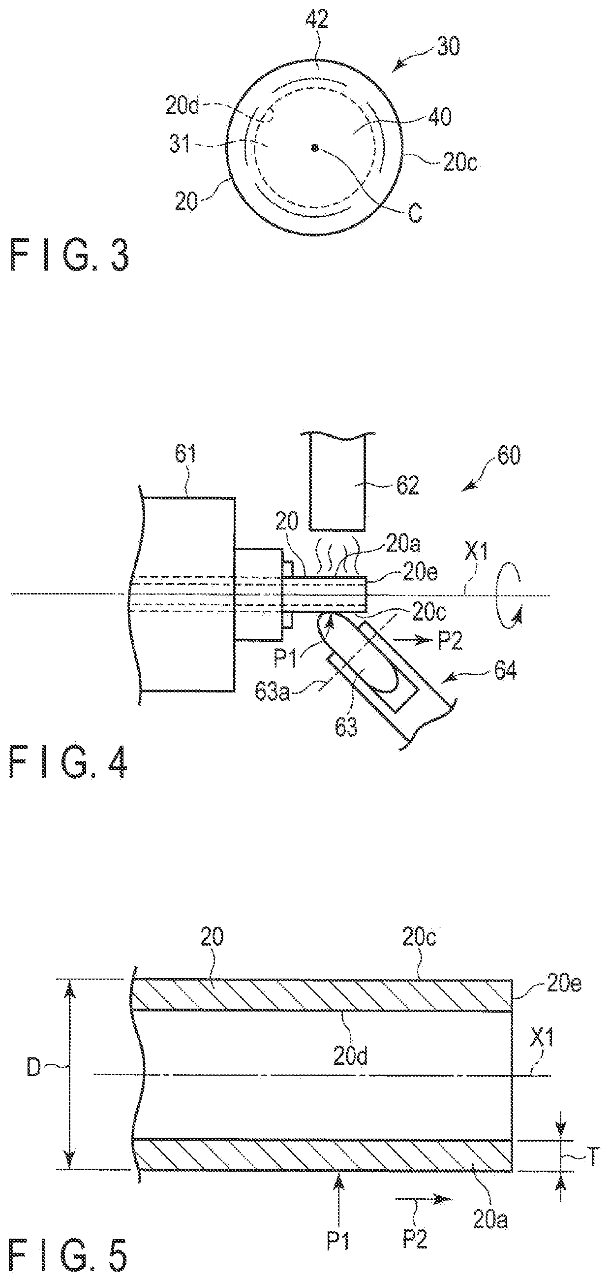
[0046]FIG. 10 shows a cross section of a terminal sealed portion 30B according to a The terminal sealed portion 30B also forms a rotationally symmetric shape in which an axis X1 of a rod 20 is a symmetric axis. More specifically, the terminal sealed portion 30B includes an end wall portion 41, an arc-shaped curved surface 42, a distal-end-center closure portion 43, and a recess 45 in a cross section along the axis X1 (symmetric axis). The end wall portion 41 includes an end face 40a, which is perpendicular to the axis X1, and is substantially flat. The arc-shaped curved surface 42 is contiguous with the end face 40a and an outer peripheral surface 20c. The distal-end-center closure portion 43 is formed on the axis X1 at the center of the end wall portion 41. The recess 45 has a rotationally symmetric shape in which the axis X1 is the symmetric axis. The center of the recess 45 (i.e., a distal end 45a of the recess 45) is located on the axis X1. A thickness at the center of the rece...

fourth embodiment

[0047]FIG. 11 shows a hollow stabilizer 80 for a vehicle according to a The hollow stabilizer 80 is an example of a hollow spring member, and is arranged in a suspension mechanism part of a vehicle. The hollow stabilizer 80 is constituted of a hollow rod 20, and includes a torsion portion 81 extending in a width direction of the vehicle, arm portions 82 and 83 extending from both ends of the torsion portion 81, and mounting portions 84 and 85. Each of the mounting portions 84 and 85 is formed by processing an end portion of the hollow rod 20 having a terminal sealed portion similar to that of the above embodiments.


PUM

PropertyMeasurementUnit
thicknessaaaaaaaaaa
length L1aaaaaaaaaa
length L2aaaaaaaaaa

Abstract

A method for manufacturing a hollow spring member having a hollow steel spring rod having terminal sealed portions at both ends thereof. Each terminal sealed portion has a rotationally symmetric shape in which an axis passing through a center of the spring rod is an axis of symmetry. Each terminal sealed portion has an end wall portion including an end face; an arc-shaped smoothly curved surface between an outer peripheral surface of the spring rod and the end face, and a hermetically closed distal-end-center closure portion on the axis passing through the center of the spring rod. The method includes forming each of the end portions of the spring rod by forming a chamfered portion on an inner or outer peripheral side of the end portion of a hollow wire, the end portion having an opening portion at a distal end, heating the end portion of the hollow wire having the chamfered portion, and spinning the heated end portion to be gathered toward the axis from the outer peripheral side by a jig. The end wall portion, which includes the distal-end-center closure portion, is formed by the distal end of the end portion being joined together on the axis.

Description

CROSS-REFERENCE TO RELATED APPLICATIONS[0001]This application is a Divisional Application of U.S. application Ser. No. 16 / 145,037, filed on Sep. 27, 2018, which is a Continuation Application of PCT Application No. PCT / JP2017 / 013098, filed Mar. 29, 2017 and based upon and claiming the benefit of priority from prior Japanese Patent Application No. 2016-068043, filed Mar. 30, 2016, the entire contents of all of which are incorporated herein by reference.BACKGROUND OF THE INVENTION1. Field of the Invention[0002]The present invention relates to a hollow spring member such as a coil spring, a stabilizer, or a torsion rod, using a hollow rod as the material.2. Description of the Related Art[0003]A suspension for a vehicle such as a car comprises a coil spring, an upper spring seat, and a lower spring seat. The upper spring seat supports an upper end of the coil spring. The lower spring seat supports a lower end of the coil spring. The coil spring is compressed between the lower spring seat...

Claims


Application Information

Patent Timeline
Patent Type & Authority Applications(United States)
IPC IPC(8): B60G21/055B60G11/14F16F1/06F16F1/14F16F1/02B60G21/045
CPCB60G21/055B60G11/14F16F1/06F16F1/14F16F1/02C21D7/06B60G2206/012B60G2206/427B60G2206/724B60G2206/81B60G2206/8403B60G21/045C21D9/02F16F1/042B60G2206/8112B60G2202/135B60G2202/12B60G2206/80B60G2206/81035B60G2206/8106B60G2206/8109B60G2202/13B60G15/062F16F2224/0208F16F2226/02F16F2234/02
Inventor UMEZAWA, MASAHIROTAKEDA, DAISUKE
Owner NHK SPRING CO LTD
Why Eureka
Try Eureka