
Electropneumatic control module

Pending Publication Date: 2022-07-21
ZF CV SYST EURO BV
View PDF0 Cites 3 Cited by
  • Summary
  • Abstract
  • Description
  • Claims
  • Application Information

AI Technical Summary

Benefits of technology

This patent is for an electropneumatic control module used in vehicle braking systems. The module has a redundancy port that serves two functions: controlling brake pressure at the trailer and providing overload protection. This means that the module can control the brakes at the trailer using the redundancy pressure and still protect the system from overload should there be a failure. By eliminating the need for a separate port, the module is simpler and cheaper to manufacture and install.

Problems solved by technology

This can result in overloading of and / or damage to the actuating unit and / or the wheel brake.
Furthermore, if excessive braking forces are used, there is a risk of a loss of control of the vehicle, for example owing to locking wheels.
Such inverse relay valves are of complex construction and commonly have multiple control pistons that interact with one another via different control surfaces and different control chambers, and are associated with high costs.
A disadvantage here is that, in order to implement an overload protection function, further pneumatic ports and / or additional lines have to be provided, which make the system more complicated and result in increased costs.
However, a cost-effective implementation of the overload protection function is not disclosed.
For example, the electronic control unit may have a fault, or a voltage supply of the electropneumatic control module may be interrupted.

Method used


Image

  • Electropneumatic control module
  • Electropneumatic control module
  • Electropneumatic control module

Examples


first embodiment

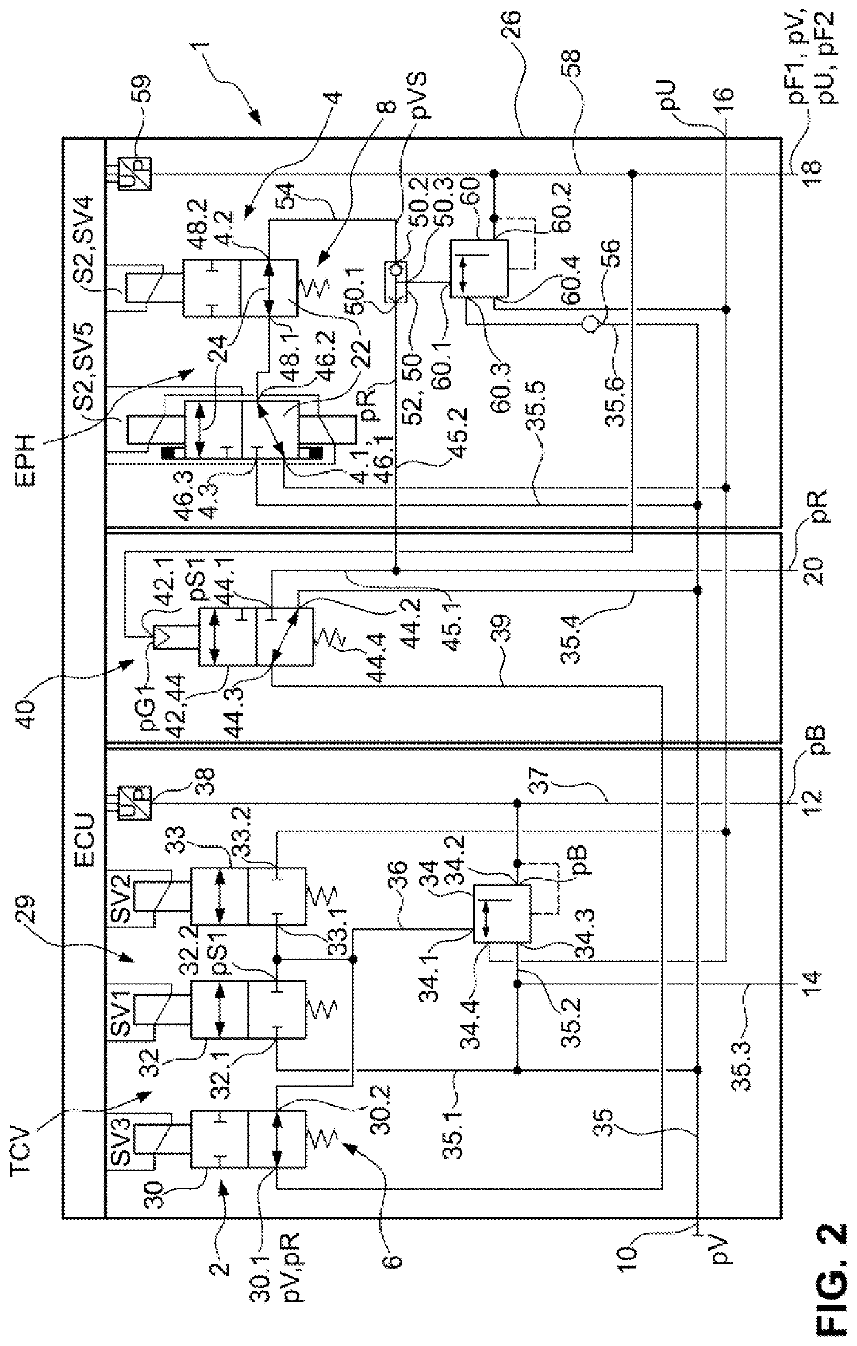
[0045]FIG. 2 shows the electropneumatic control module 1, which has a trailer control unit TCV, a holding brake unit EPH and a parking brake valve unit 40. The trailer control unit TCV, the holding brake unit EPH and the parking brake valve unit 40 are in this case integrated into a common housing 26. The trailer control unit TCV, which is also referred to as trailer control valve, and the holding brake unit EPH are configured here to be electronically controllable, and are connected to the electronic control unit ECU. The parking brake valve unit 40 has a first pneumatically controlled switching valve 42, which can be controlled via a first control pressure pS1 provided at a first pneumatic control port 42.1.

[0046]The first pneumatic control port 42.1 is connected in pressure-conducting fashion to the spring-type actuator port 18, such that the first control pressure pS1 is equivalent to a pressure provided at the spring-type actuator port 18. Here, the first pneumatically controll...

second embodiment

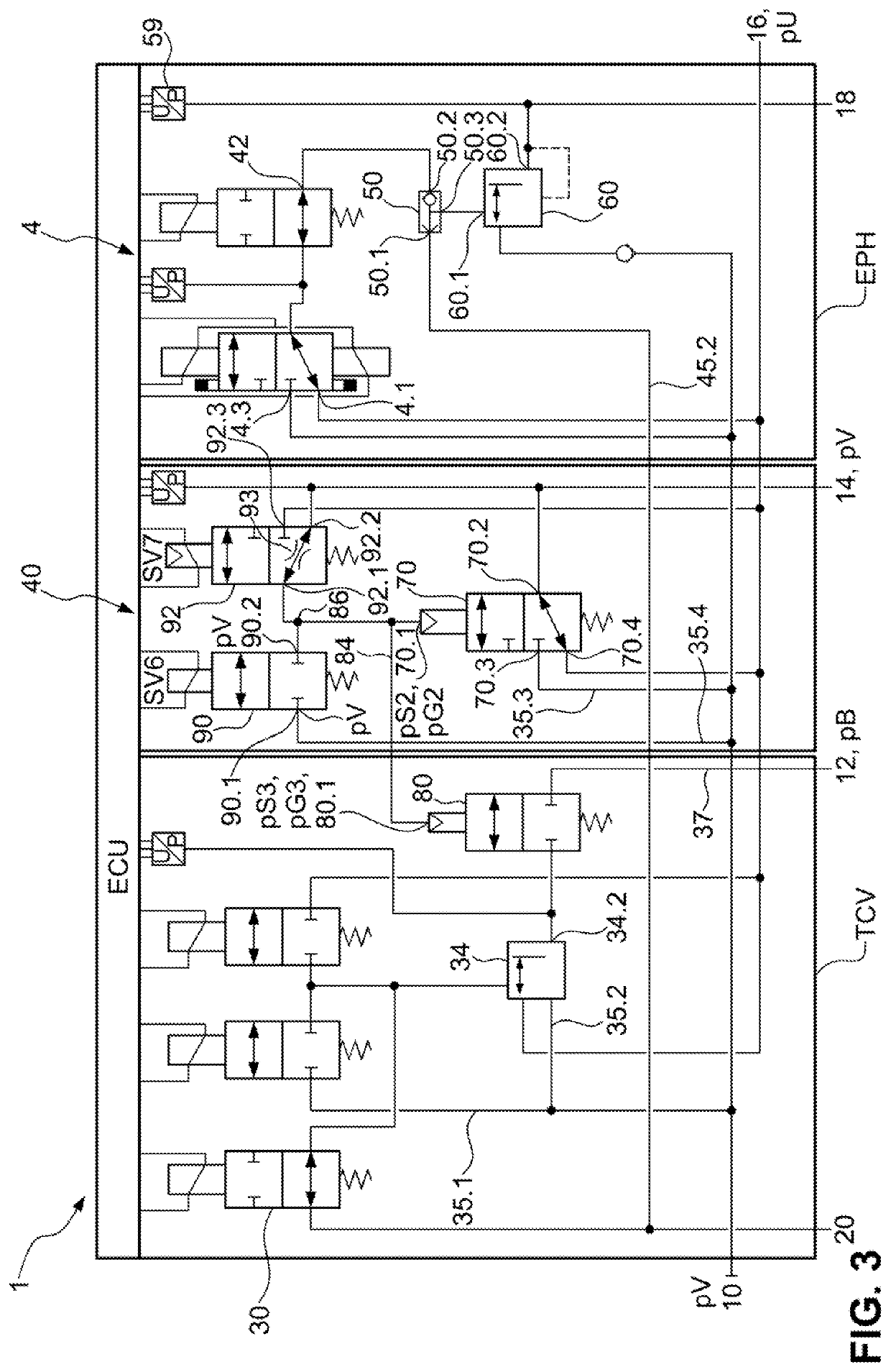
[0065]A major function of the parking brake valve unit 40 includes protecting a pressure level in the electropneumatic control module 1 and in the electronically controllable brake system 204 in the event of a leak in a brake system of the trailer (not illustrated) or in the event of a sudden disconnection of the trailer from the trailer feed pressure port 14. In such a situation, the trailer feed pressure port 14 is rapidly ventilated. If, in such a situation, the second pneumatic switching valve 70 were to remain in the first switching position, then the compressed air supply 250 connected to the supply port would be evacuated. This is avoided by way of the described arrangement of the first parking brake valve 90, of the second parking brake valve 92, of the second pneumatic switching valve 70 and of the third pneumatic switching valve 80. If the trailer feed port 14 is ventilated, then the pressure of the second port 92.2, which is connected thereto, of the second parking brake...


PUM


Abstract

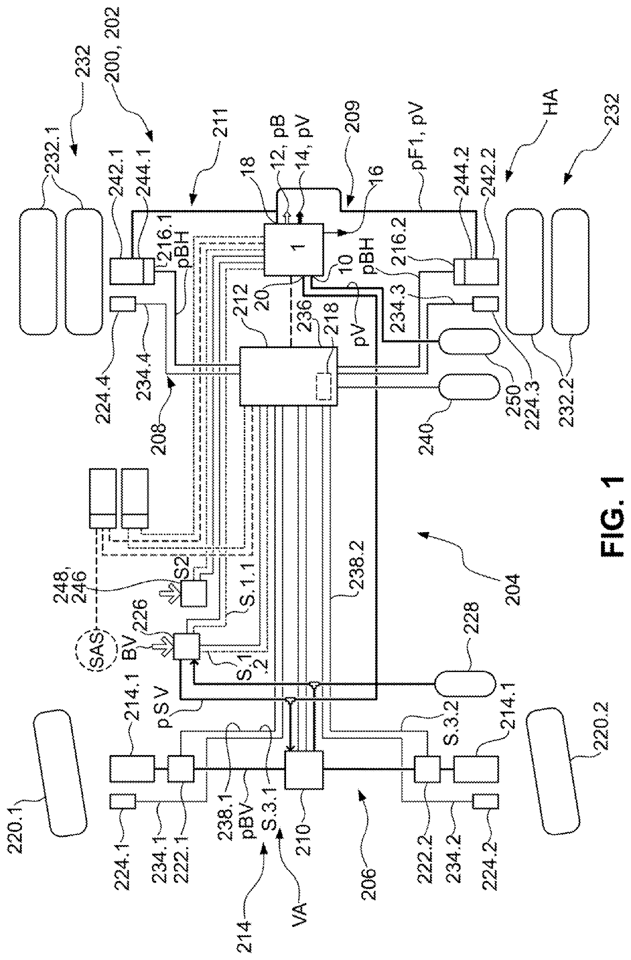
An electropneumatic control module has a trailer control unit, which has a trailer brake pressure port and a trailer feed pressure port, a holding brake unit, which has a spring-type actuator port and a holding brake pilot control unit, and an electronic control unit, which switches a holding brake pilot control unit into a ventilation position, wherein a second holding brake pilot control port is connected in pressure-conducting manner to a first holding brake pilot control port and the spring-type actuator port is connectable to a vent. The holding brake unit is connected to a redundancy port and is configured to output a first holding brake pressure at the spring-type actuator port when the holding brake pilot control unit is in the ventilation position and a redundancy pressure is provided. The trailer control unit outputs a brake pressure at the trailer brake pressure port when a redundancy pressure is provided.

Description

CROSS REFERENCE TO RELATED APPLICATIONS[0001]This application is a continuation application of international patent application PCT / EP2020 / 080638, filed Nov. 2, 2020 designating the United States and claiming priority from German application 10 2019 130 762.7, filed Nov. 14, 2019, and the entire content of both applications is incorporated herein by reference.TECHNICAL FIELD[0002]The disclosure relates to an electropneumatic control module for an electronically controllable pneumatic brake system of a vehicle, in particular utility vehicle, having a pneumatic supply port, which can be connected to a compressed air supply for the purposes of receiving a supply pressure, a trailer control unit, which has a trailer control valve unit with one or more electropneumatic valves, a trailer brake pressure port and a trailer feed pressure port, a holding brake unit, which has a spring-type actuator port for at least one spring-type actuator of the vehicle and has a holding brake pilot control...

Claims


Application Information

Patent Timeline
IPC IPC(8): B60T13/38B60T13/68B60T8/171B60T8/17
CPCB60T13/385B60T13/683B60T2270/88B60T8/1708B60T2270/413B60T8/171B60T13/662B60T7/20B60T15/181
Inventor KLOSTERMANN, THILOVAN THIEL, JULIAN
Owner ZF CV SYST EURO BV
Learn More