Magnetoresistive element having a composite recording structure

Pending Publication Date: 2022-07-28
GUO YIMIN +2
View PDF9 Cites 3 Cited by
  • Summary
  • Abstract
  • Description
  • Claims
  • Application Information

AI Technical Summary

Benefits of technology

[0009]According to a second embodiment of the present disclosure, the FL2 is made of Co/Ni superlattice, and the cap layer is a metal layer having a FCC crystal structure such as NiCr or a HCP crystal structure such as Ru. After a thermal annealing process, a multilayered structure [Co/Ni]n, where n is a small positive integer, forms a better Co/Ni superlattice for a strong perpendicular magnetic anisotropy. Since the FL2 contains Ni atoms, it has a sufficient high damping constant for a fast STT-driven magnetization reversal. A third embodiment of the present disclosure is similar to the second embodiment except that an insertion layer provided between

Problems solved by technology

However, for random-access-memory (RAM) like applications, this technology faces various challenges along with its merits,

Method used


Image

  • Magnetoresistive element having a composite recording structure
  • Magnetoresistive element having a composite recording structure
  • Magnetoresistive element having a composite recording structure

Examples


first embodiment

of Current Invention

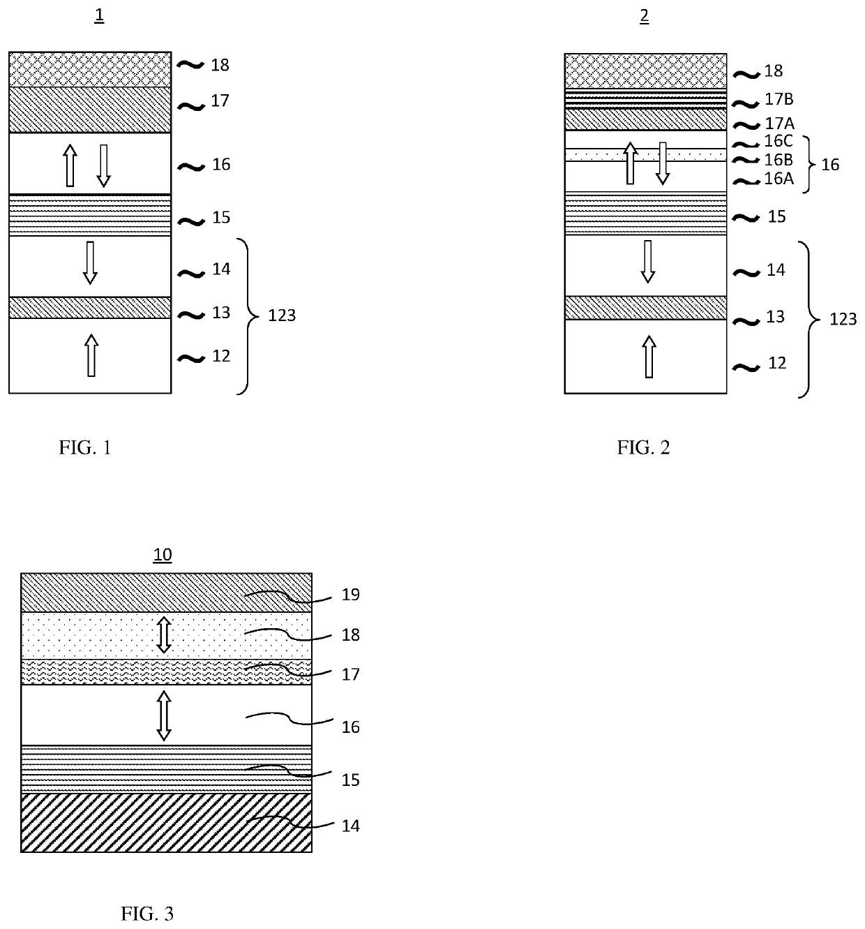
[0038]FIG. 3 is a cross-sectional view showing a configuration of an MTJ element 10 as deposited according to the first embodiment in this invention. The MTJ element 10 is configured by stacking a reference structure 14, a tunnel barrier layer 15, a composite recording structure comprising a first free layer (FL1) 16, a nonmagnetic spacing layer 17 and a second free layer (FL2) 18 and a cap layer 19 in the order from the bottom to the top.

[0039]The FL1 is made of a ferromagnetic material and FL2 is made of a Ni-containing ferromagnetic material. Magnetizations of FL1 (16) and FL2 (18) are parallel-coupled across the nonmagnetic spacing layer 17. Both of the FL1 and FL2 have perpendicular magnetic anisotropies and variable (reversible) magnetization directions. The reference structure has an invariable (fixing) magnetization direction. The reference structure is a synthetic anti-ferromagnetic structure having a perpendicular magnetic anisotropic energy which is su...

second embodiment

of Current Invention

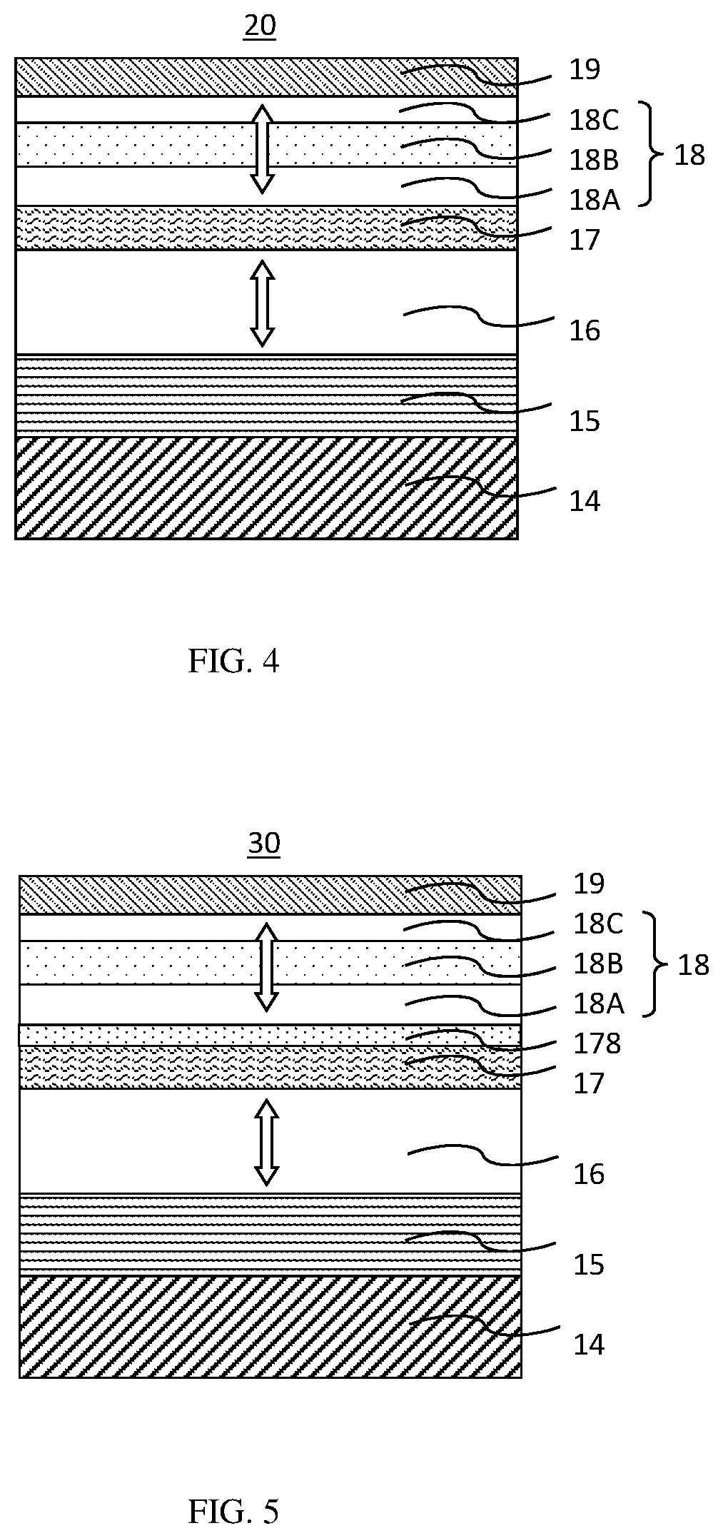
[0043]FIG. 4 is a cross-sectional view showing an example configuration of an MTJ element 20 as deposited according to the second embodiment. The MTJ element 20 is configured by stacking a reference structure 14, a tunnel barrier layer 15, a composite recording structure comprising a first free layer (FL1) 16, a nonmagnetic spacing layer 17, a second free layer (FL2) 18 having a super-lattice structure and a cap layer 19 in the order from the bottom to the top.

[0044]The FL1 is made of a ferromagnetic material and FL2 is made of a Ni-containing ferromagnetic material. Magnetizations of FL1 (16) and FL2 (18) are parallel-coupled across the nonmagnetic spacing layer 17. Both of the FL1 and FL2 have perpendicular magnetic anisotropies and variable (reversible) magnetization directions. The reference structure has an invariable (fixing) magnetization direction. The reference structure is a synthetic anti-ferromagnetic structure having a perpendicular magnetic anisotro...

third embodiment

of Current Invention

[0048]FIG. 5 is a cross-sectional view showing a configuration of an MTJ element 30 as deposited according to the third embodiment. The MTJ element 30 is configured by stacking a reference structure 14, a tunnel barrier layer 15, a recording structure 16 comprising a first free layer (FL1) 16, a nonmagnetic spacing layer 17, an insertion layer 178, a second free layer (FL2) 18 having a super-lattice structure and a cap layer 19 in the order from the bottom to the top.

[0049]The FL1 is made of a ferromagnetic material and FL2 is made of a Ni-containing ferromagnetic material. Magnetizations of FL1 and FL2 are parallel-coupled across the nonmagnetic spacing layer 17. Both of the FL1 and FL2 have perpendicular magnetic anisotropies and variable (reversible) magnetization directions. The reference structure has an invariable (fixing) magnetization direction. The reference structure is a synthetic anti-ferromagnetic structure having a perpendicular magnetic anisotropic...


PUM


Abstract

A method of forming a bottom-pinned magnetoresistive element comprising a composite recording structure that includes a first magnetic free layer and a second magnetic free layer containing Ni atoms, separated by an oxide spacing layer. The first magnetic free layer is Ni-free and the first magnetic free layer and the second magnetic free layer are magnetically parallel-coupled. A magnetic STT-enhancing structure is further provided atop the cap layer, wherein the magnetic STT-enhancing structure comprises a first magnetic material layer atop the cap layer and having a perpendicular magnetic anisotropy and an invariable magnetization anti-parallel to the magnetization direction of the reference layer, a second anti-ferromagnetic coupling (AFC) layer atop the first magnetic material layer, and a second magnetic material layer atop the second AFC layer.

Description

BACKGROUND OF THE INVENTION1. Field of the Invention[0001]This invention relates to the field of magnetoresistive elements. More specifically, the invention comprises magnetic-random-access memory (MRAM) using magnetoresistive elements with composite recording structures having additional Ni-containing magnetic free layers for fast writing and low powers as basic memory cells which potentially replace the conventional semiconductor memory used in electronic chips, especially mobile chips for power saving and non-volatility as well as memory blocks in processor-in-memory (PIM).2. Description of the Related Art[0002]In recent years, magnetic random access memories (hereinafter referred to as MRAMs) using the magnetoresistive effect of ferromagnetic tunnel junctions (also called MTJs) have been drawing increasing attention as the next-generation solid-state nonvolatile memories that can cope with high-speed reading and writing, large capacities, and low-power-consumption operations. A ...

Claims


Application Information

Patent Timeline
IPC IPC(8): H01L43/12H01L43/10H01L43/02
CPCH01L43/12H01L43/02H01L43/10H10N50/01H10N50/85H10N50/10H10N50/80
Inventor GUO, YIMINXIAO, RONGFUCHEN, JUN
Owner GUO YIMIN
Why Eureka
Try Eureka