Subsea Seawater Filtration Apparatus

a technology of filtration apparatus and seawater, which is applied in the direction of filtration, water/sewage treatment by degassing, membranes, etc., can solve the problems of large footprint, large footprint, and large footprint of filtration system, and achieves large footprint/weight requirements, high operating costs associated with intervention, cleaning and replacement, and complex filtration assembly

Active Publication Date: 2022-08-04
FMC TECH INC
View PDF5 Cites 0 Cited by
  • Summary
  • Abstract
  • Description
  • Claims
  • Application Information

AI Technical Summary

Benefits of technology

[0008]In accordance with one embodiment, the filtration apparatus also includes an intake pipe which is fluidly connected to the intake collection chamber, a discharge pipe which is fluidly connected to the discharge collection chamber and a reject pipe which is fluidly connected to the reject collection chamber. The intake, discharge and reject pipes may be a single multibore connector which is configured to couple to a corresponding multibore connector hub which is located, e.g., below the second end of the casing when the filtration apparatus is oriented vertically. This arrangement substantially reduces the footprint of the filtration apparatus and facilitates the installation and retrieval of the apparatus from a surface vessel.
[0009]In accordance with another embodiment, each filtration membrane stack comprises a number of filtration membranes, each of which is sealed to a corresponding hole in a corresponding partition plate. Each filtration membrane comprises an inlet end and an outlet end, and the outlet end is spaced apart from an adjacent partition plate located closer to the second end. Thus, the reject fluid from each filtration membrane is allowed to flow into the chamber formed by the two partition plates before entering the inlet end of the succeeding filtration membranes. As a result, if one filtration membrane should become clogged, that filtration membrane will not clog the entire filtration membrane stack.
[0010]The present disclosure is also directed to a membrane-based water filtration system for removing sulfates and other multi-valent ions from a liquid, including but not limited to seawater, groundwater, produced water, or a mixture thereof. The improved NF membrane disclosed herein uses a special coating to enhance the separation efficiency by increasing flux, providing better selectivity and increased rejection, reducing fouling, and increasing tolerance to chemical cleaning. The improved NF membrane is particularly useful for removing sulfates from water sources for the purpose of water injection, such as in improved oil recovery (IOR) or enhanced oil recovery (EOR) operations. In such applications, the improved water quality results in additional recovery from the reservoir, avoidance of scale in the reservoir and facilities, avoidance of souring due to the proliferation of sulfate-reducing bacteria (SRB's), and better efficiency of the EOR chemicals.
[0011]The water filtration system comprising the improved NF membrane of the present disclosure is also a superior alternative to existing sulfate removal systems installed in onshore and offshore facilities and facilitates installation of a subsea water injection facility. The NF membrane is suitable for new build systems and for retrofitting existing sulfate removal units (SRU). The application of water treatment systems incorporating the improved NF membrane will significantly increase the applicability of such systems on the basis of water quantity / quality, footprint / weight requirements, chemical use and operability, and marketability in the oil and gas industry.
[0012]The water filtration system of the present disclosure includes at least one NF membrane element which is modified with a super-hydrophilic coating that can improve NF permeability by at least 25%, as well as improve foulant repulsion capability and chlorine tolerance, without compromising, and possibly even improving, sulfate rejection. The coated NF membrane significantly lowers chemical consumption (thus reducing chemical storage footprint) and frequency of cleaning intervention. The coating is applicable to various commercially available membranes of different geometry and materials. In addition, a re-coating system is designed to be put into operation (if necessary) when the efficacy of the initial coating degrades due to exposure to fouling or cleaning chemicals. The re-coating operation can be implemented after conventional chemical cleaning is applied. The recoating rig is fully integrated into the chemical cleaning system, thus requiring minimal additional footprint and a simple adjustment to the conventional chemical cleaning rig. The reduction in chemical consumption due to the reduction in cleaning frequency and the elimination of the need for a de-chlorination step can compensate for the additional footprint allotted for recoating chemicals.
[0013]The disclosed water filtration system involves passing the water through an improved nano-filtration (“NF”) membrane having, preferably, at least 25% higher permeability than the prior art, thus enabling applicability and ease of deployment for both topside and subsea sulfate removal units. These improvements are suitable for designing new NF systems and for retrofitting existing systems to improve productivity. The resulting NF systems require less footprint, which enables their application on space and weight constrained platforms.

Problems solved by technology

In this arrangement, the large stacks of horizontally oriented casings and the external piping assembly required to connect the casings to the collector contribute to a filtration assembly which is relatively complex and heavy and comprises a relatively large footprint.
Consequently, such filtration system are impractical for use subsea.
Large footprint / weight requirements and high operating costs associated with intervention, cleaning and replacement are currently the key limiting factors to the use of nano-filtration (NF) membranes in seawater filtration systems, especially in offshore (both topside and subsea) facilities.
These membranes have the tendency to suffer from severe fouling due to the accumulation of particulate / colloidal, organic and / or biological matter, resulting in reduced water productivity and / or high operational costs (e.g., for chemical cleaning or replacement).
The combination of reduced membrane permeability, frequent downtime and high chemical consumption due to fouling translates directly to lower productivity and high operational expenditures (OPEX).

Method used


Image

  • Subsea Seawater Filtration Apparatus
  • Subsea Seawater Filtration Apparatus
  • Subsea Seawater Filtration Apparatus

Examples


Embodiment Construction

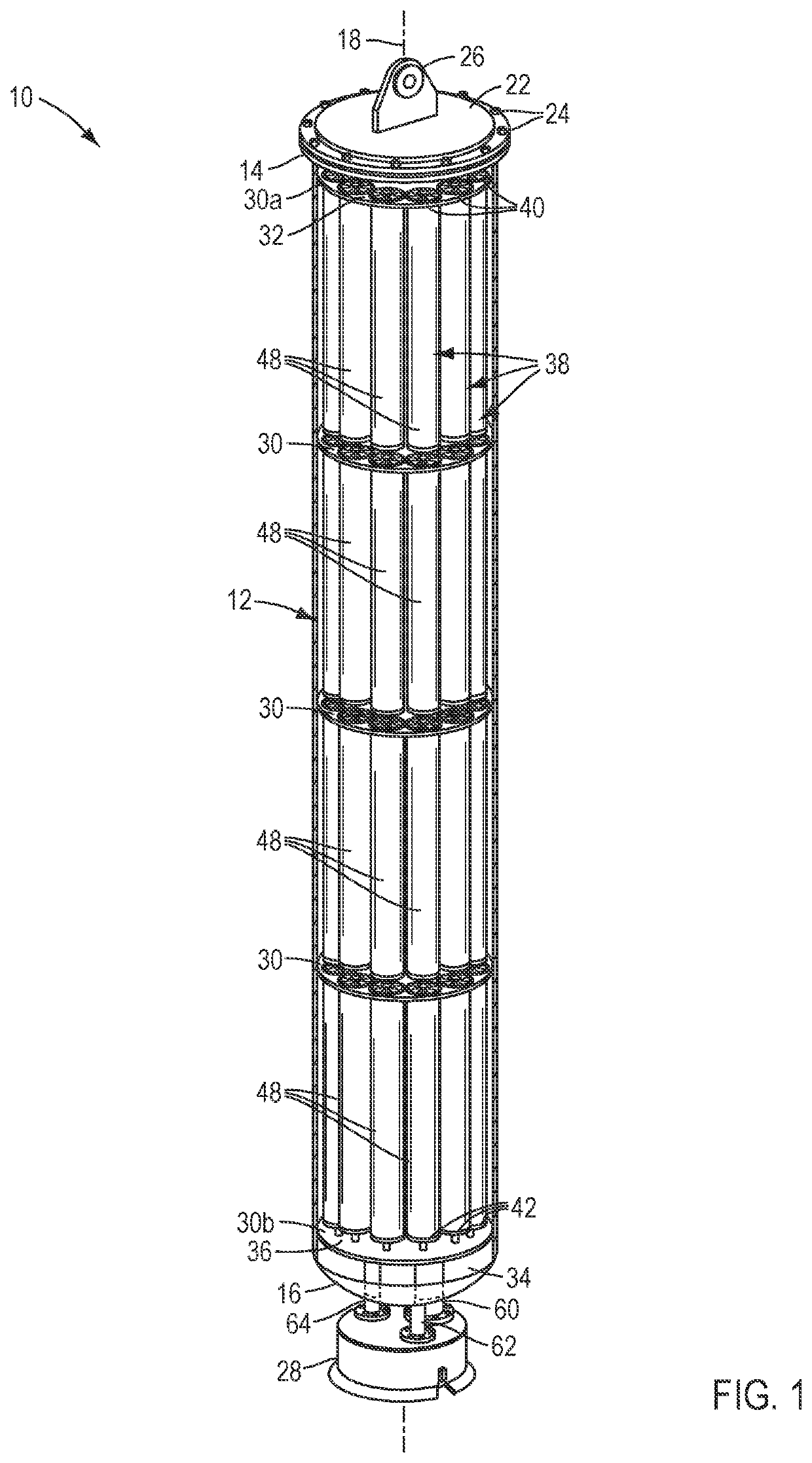
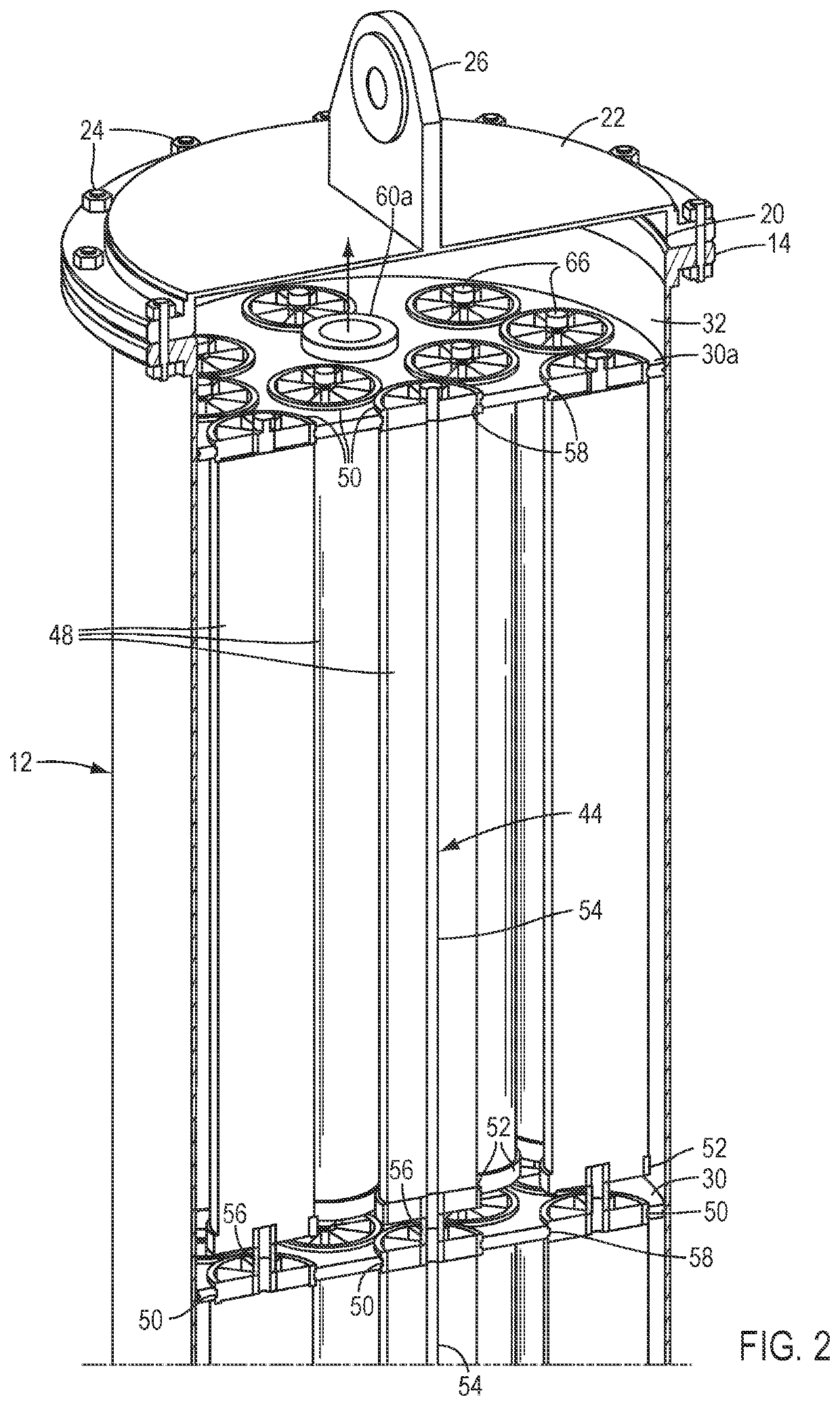
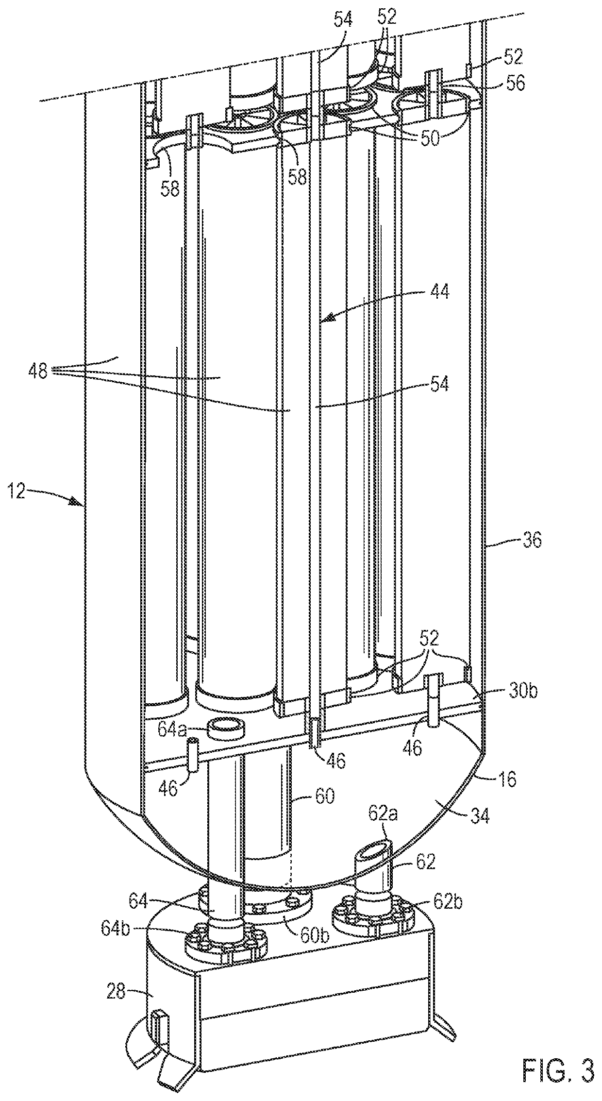
[0021]A general embodiment of the filtration apparatus of the present disclosure comprises a tubular casing comprising a longitudinal axis and first and second ends, a plurality of elongated filtration membrane stacks positioned side-by-side in the casing generally parallel to the longitudinal axis, and a plurality of partition plates positioned in the casing and preferably sealed thereto to thereby define an intake collection chamber between a first of the partition plates and the first end, a discharge collection chamber between a second of the partition plates and the second end, and a reject collection chamber opposite the second partition plate from the second end. Each filtration membrane stack comprises an intake end which is fluidly connected to the intake collection chamber, a discharge end which is fluidly connected to the reject collection chamber, and a permeate channel which extends between the first and second ends and is fluidly connected to the discharge collection c...


PUM

PropertyMeasurementUnit
wt %aaaaaaaaaa
thicknessaaaaaaaaaa
hydrophilicaaaaaaaaaa

Abstract

A filtration apparatus includes a tubular casing having a longitudinal axis and first and second casing ends, a plurality of partition plates positioned in the casing and sealed thereto to thereby define an intake collection chamber between a first of said partition plates and the first casing end, a discharge collection chamber between a second of said partition plates and the second casing end, and a reject collection chamber opposite the second partition plate from the second casing end, a plurality of elongated filtration membrane stacks positioned side-by-side in the casing generally parallel to the longitudinal axis, each filtration membrane stack comprising an intake end fluidly connected to the intake collection chamber, a discharge end fluidly connected to the reject collection chamber, and a permeate channel extending between the first and second ends and fluidly connected to the discharge collection chamber. The filtration apparatus also includes an intake pipe connected to the intake collection chamber, a discharge pipe connected to the discharge collection chamber, and a reject pipe connected to the reject collection chamber. Each filtration membrane stack is made of a plurality of filtration membranes which are each sealed to a corresponding hole in a corresponding partition plate, each filtration membrane having an inlet end and an outlet end and being sealed to the corresponding hole between the inlet and outlet ends, and the outlet end being spaced apart from an adjacent partition plate located closer to the second casing end.

Description

[0001]The present application is a divisional of U.S. patent application Ser. No. 16 / 619,072 filed on Dec. 3, 2019, which is a U.S. national stage filing of International Patent Application No. PCT / US2017 / 038752 filed on Jun. 2, 2017.[0002]The present disclosure relates to a seawater filtration apparatus which comprises multiple filtration membrane stacks. In one embodiment, the disclosure is directed to a seawater filtration apparatus which comprises multiple filtration membrane stacks positioned in a single vertical casing through which the intake, reject and discharge pipes are also routed. The present disclosure is also directed to an improved filtration membrane and a filtration system which comprises such a membrane.BACKGROUND OF THE INVENTION[0003]Filtration assemblies are commonly used in the subsea hydrocarbon production industry to filter certain minerals from raw seawater prior to injecting the seawater into the hydrocarbon formation for artificial lift applications. Such...

Claims


Application Information

Patent Timeline
Patent Type & Authority Applications(United States)
IPC IPC(8): B01D63/06B01D61/02B01D61/08B01D65/02B01D65/08C02F1/44C02F1/76
CPCB01D63/06C02F2103/08B01D61/027B01D61/08B01D65/02B01D65/08C02F1/442C02F1/76B01D2311/12B01D2311/2649B01D2313/04B01D2313/08B01D2313/18B01D2313/20B01D2319/025B01D2319/04B01D2321/08B01D2321/168B01D61/022B01D61/58B01D2313/19B01D2319/02C02F1/001C02F1/20C02F1/444C02F2303/14C02F2303/22B01D2313/13B01D2319/022B01D2313/105Y02A20/131C02F2303/16C02F2303/20B01D63/069B01D61/0271B01D61/026
Inventor STRIKOVSKI, ANDREIDAVALATH, JANARDHANSHAH, ABHISHEKVILLACORTE, LOREEN OPLEVERBEEK, PAULKREBS, THOMASMEHROTRA, VIVEKGANGULI, RAHUL
Owner FMC TECH INC
Why Eureka
Try Eureka