METHOD FOR PRODUCING Cu-Ni-Sn ALLOY

Pending Publication Date: 2022-09-08
NGK INSULATORS LTD
View PDF2 Cites 0 Cited by
  • Summary
  • Abstract
  • Description
  • Claims
  • Application Information

AI Technical Summary

Benefits of technology

The invention provides a method for producing a copper-nickel-tin alloy (Cu-Ni-Sn alloy) that reduces internal cracks and uniformly disperses tin (Sn) in the alloy, by using a combination of mist cooling and immersion cooling. This method improves both the productivity and product quality of the alloy.

Problems solved by technology

For example, when the cooling speed is fast, internal cracks occur in the ingot to deteriorate the product quality of the alloy to be obtained.
By contrast, when the cooling speed is slow, the internal cracks in the ingot can be suppressed, but cooling requires a time, and therefore the productivity of the alloy to be obtained becomes poor.
For example, when the ingot is cooled with a water-cooling shower, by immersion into a water tank, or the like, which is a cooling method which has been performed in the past, the internal cracks are liable to occur in the ingot because the cooling speed is too fast.
Even when the cooling speed is slowed by, for example, air-cooling in order to suppress the occurrence of the internal cracks, cooling requires 12 hours or longer in some cases, and therefore the productivity is remarkably poor.
The segregation of Sn is more unlikely to occur when the cooling speed is faster, but as described above, when the cooling speed is fast, the internal cracks are liable to occur in the ingot.
As described above, the internal cracks and the segregation of Sn are liable to occur in a copper alloy containing Sn having a low melting point, and among the copper alloys containing Sn, when the Cu-15Ni-8Sn alloy with a high Sn content is produced, the influence of the cooling condition (for example, cooling speed) of the ingot on the productivity and product quality of the alloy to be obtained is particularly large.

Method used


Image

  • METHOD FOR PRODUCING Cu-Ni-Sn ALLOY
  • METHOD FOR PRODUCING Cu-Ni-Sn ALLOY
  • METHOD FOR PRODUCING Cu-Ni-Sn ALLOY

Examples


example 1

[0046]Cu-15Ni-8Sn alloy defined as UNS: C72900 was prepared as a Cu—Ni—Sn alloy and evaluated by the following procedures.

[0047](1) Weighing

[0048]A pure Cu nugget, a Nickel metal, a Sn metal, manganese tourmaline, and a Cu—Ni—Sn alloy scrap, which are raw materials for a Cu—Ni—Sn alloy, were weighed in such a way as to obtain an objective composition. That is, Cu in an amount of 163 kg, Ni in an amount of 30 kg, Sn in an amount of 15 kg, and the Cu—Ni—Sn alloy scrap in an amount of 1450 kg were weighed and mixed to be thereby formulated.

[0049](2) Melting and Slag Treatment

[0050]The weighed raw materials for a Cu—Ni—Sn alloy were melted in a high-frequency melting furnace for atmospheric air at 1300 to 1400° C. and stirred for 30 minutes to homogenize the components. Slag scraping and slag scooping were performed after completion of melting.

[0051](3) Component Analysis (Before Casting)

[0052]Part of the Cu—Ni—Sn alloy obtained by performing the melting and the slag treatment was taken...

example 2 (

Comparison)

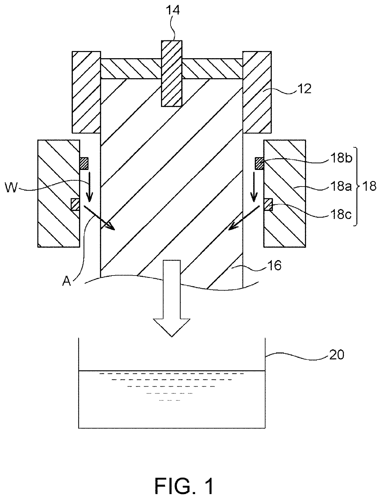
[0065]Preparation and evaluations of a sample were performed in the same manner as in Example 1, except that only the immersion cooling was performed in the following manner in place of the mist cooling and the immersion cooling of (5) described above. The obtained cast product had a size of 320 mm in diameter×2 m in length.

[0066](Immersion Cooling)

[0067]The ingot 16 whose surface layer had been solidified was directly immersed in the water tank 20 and cooled in water without spraying water W and without blowing air A with the cooler 18 provided immediately below the mold 12. In addition, the ingot 16 was lowered while being received by a receiving table (not shown) which was lowered at a speed of 25 to 35 mm / min. By such a cooling method, the ingot 16 was cooled to 50° C. or lower within 20 minutes after the semi-continuous casting of (4) described above.

example 3 (

Comparison)

[0068]Preparation and evaluations of a sample were performed in the same manner as in Example 1, except that the water cooling with a cooler was performed in the following manner in place of the mist cooling and the immersion cooling of (5) described above. The obtained cast product had a size of 320 mm in diameter×2 m in length.

[0069](Water Cooling with Cooler)

[0070]Liquid water was sprayed, with the cooler 18 provided immediately below the mold 12, on the ingot 16 whose surface layer had been solidified. It is to be noted that on that occasion, air A was not blown from the air ejection part 18c, and the ingot 16 was not immersed in the water tank 20. By such a cooling method, the ingot 16 was cooled to 50° C. or lower within 30 minutes after the semi-continuous casting of (4) described above.


PUM

PropertyMeasurementUnit
Temperatureaaaaaaaaaa
Percent by massaaaaaaaaaa

Abstract

The present invention provides a method for producing a Cu—Ni—Sn alloy, which achieves both productivity and product quality by reducing internal cracks and dispersing Sn uniformly while shortening the time for cooling an ingot. The method for producing a Cu—Ni—Sn alloy is a method for producing a Cu—Ni—Sn alloy by a continuous casting method or a semi-continuous casting method, the method including: pouring a molten Cu—Ni—Sn alloy from one end of a mold, both ends of which are open, and continuously drawing out the alloy as an ingot from the other end of the mold while solidifying a part of the alloy, the part being near the mold; performing primary cooling by spraying a liquid mist on the drawn-out ingot; and performing secondary cooling by immersing the ingot having been subjected to the primary cooling in a liquid, thereby making a cast product of the Cu—Ni—Sn alloy.

Description

CROSS-REFERENCE TO RELATED APPLICATION[0001]This application claims priority to Japanese Patent Application No. 2021-033605 filed Mar. 3, 2021, the entire contents of which are incorporated herein by reference.BACKGROUND OF THE INVENTION1. Field of the Invention[0002]The present invention relates to a method for producing a Cu—Ni—Sn alloy.2. Description of the Related Art[0003]In the past, a copper alloy, such as a Cu—Ni—Sn alloy, has been produced by a continuous casting method or a semi-continuous casting method. The continuous casting method as well as the semi-continuous casting method is one of the main casting methods and is such that a molten metal is poured into a water-cooled mold to be solidified continuously and drawn out as an ingot having a certain shape (such as a rectangular shape or a round shape), and the ingot is drawn out downward in many cases. This method produces an ingot in a perfectly continuous manner and therefore is excellent in producing a large amount of...

Claims


Application Information

Patent Timeline
IPC IPC(8): B22D11/00B22D11/124C22C9/06C22C1/02
CPCB22D11/004B22D11/1246C22C9/06C22C1/02B22D11/124C22C9/02B22D11/049B22D11/225B22D11/1241
Inventor ISHII, KENSUKE
Owner NGK INSULATORS LTD
Why Eureka
Try Eureka