
Abrasive water jet full-section cutting type cutter head and application devices

a technology of abrasive water jet and a cutter head, which is applied in the direction of blast generation devices, abrasive devices, manufacturing tools, etc., can solve the problems of mechanical rock breaking and demolition methods, low efficiency, and high cos

Pending Publication Date: 2022-10-06
SHANDONG UNIV
View PDF4 Cites 0 Cited by
  • Summary
  • Abstract
  • Description
  • Claims
  • Application Information

AI Technical Summary

Benefits of technology

The present patent is about a new method for processing materials using abrasive water jets. The system has a rotating cutter head and a rotating rotor with a nozzle to cut the material. The method has the benefits of high efficiency, low energy loss, no tool wear, low bearing load, good material adaptability, low pump load, less dust and little processing heat. It can cut materials into fragments of a predetermined size with a few nozzles, making the process faster and more efficient than traditional methods.

Problems solved by technology

Therefore, tools are prone to wear during the process of tunneling, and frequent tool changes are required, resulting in high cost and low efficiency.
In addition, the mechanical rock breaking and demolition methods also have disadvantages, such as excessive bearing load, more dust, and higher operating temperature.
A water jet-assisted mechanical rock breaking and demolition method expands micro-cracks on rock or buildings with the help of high-pressure water wedge action based on the mechanical rock breaking and demolition methods, thereby reducing the stress of a cutter head, lowering the working temperature and eliminating dust, but because its core working principle is the same as that of the mechanical rock breaking and demolition methods, the problems of large tool wear, high bearing load and the like also cannot be completely solved.

Method used


Image

  • Abrasive water jet full-section cutting type cutter head and application devices
  • Abrasive water jet full-section cutting type cutter head and application devices
  • Abrasive water jet full-section cutting type cutter head and application devices

Examples


Embodiment Construction

[0032]It should be pointed out that the following detailed descriptions are all exemplary and aim to further illustrate the present disclosure. Unless otherwise specified, all technological and scientific terms used in the present disclosure have the same meanings generally understood by those of ordinary skill in the art of the present disclosure.

[0033]It should be noted that the terms used herein are merely for describing specific embodiments, but are not intended to limit exemplary embodiments according to the present disclosure. As used herein, unless otherwise clearly stated in the present disclosure, the singular form is also intended to include the plural form. In addition, it should also be understood that when the terms “include” and / or “comprise” are used in the Description, they indicate features, steps, operations, devices, components, and / or combinations thereof.

[0034]As introduced in the background art, in the fields of hard rock tunneling or building demolition, mecha...


PUM

PropertyMeasurementUnit
angleaaaaaaaaaa
angleaaaaaaaaaa
angleaaaaaaaaaa

Abstract

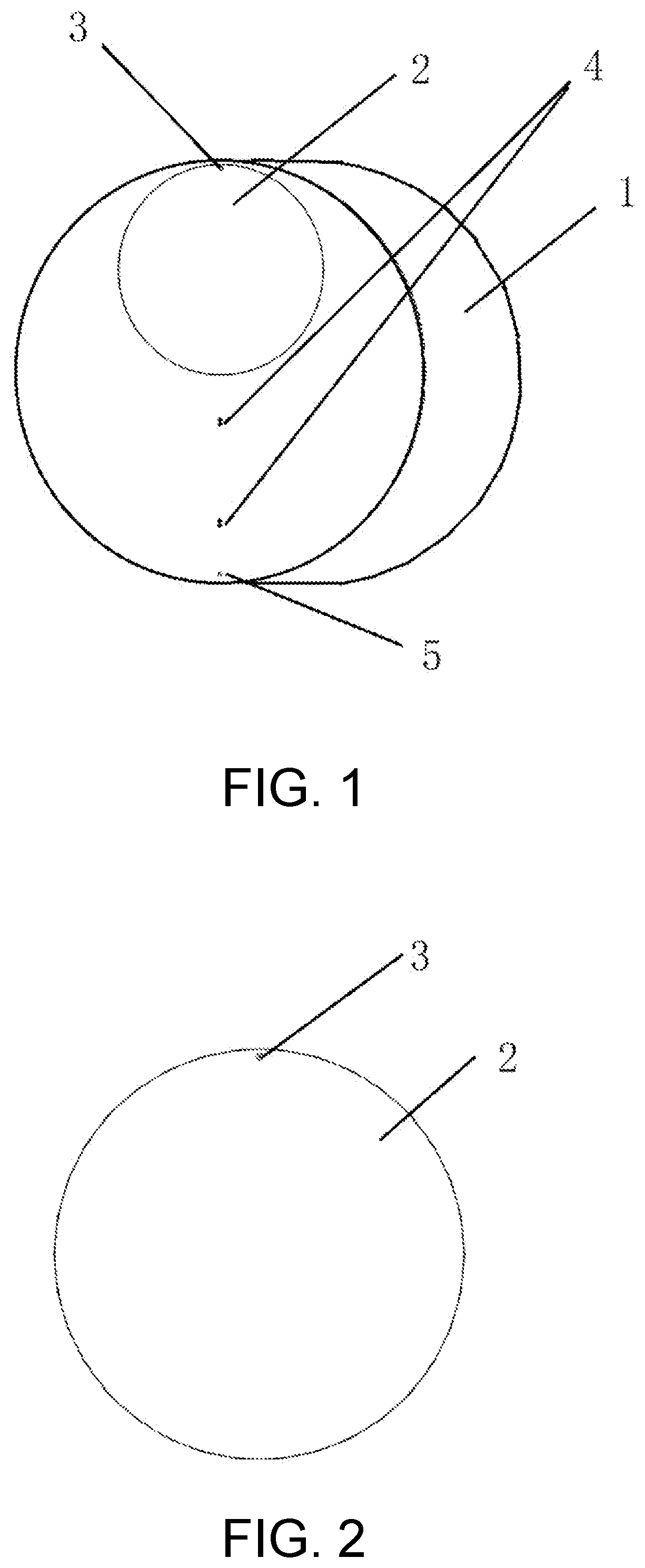
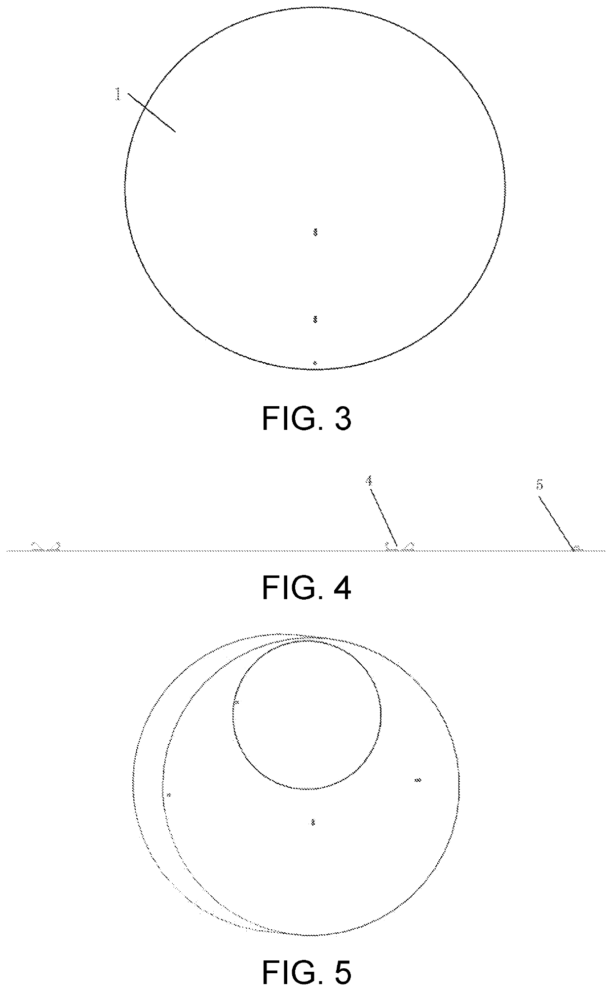
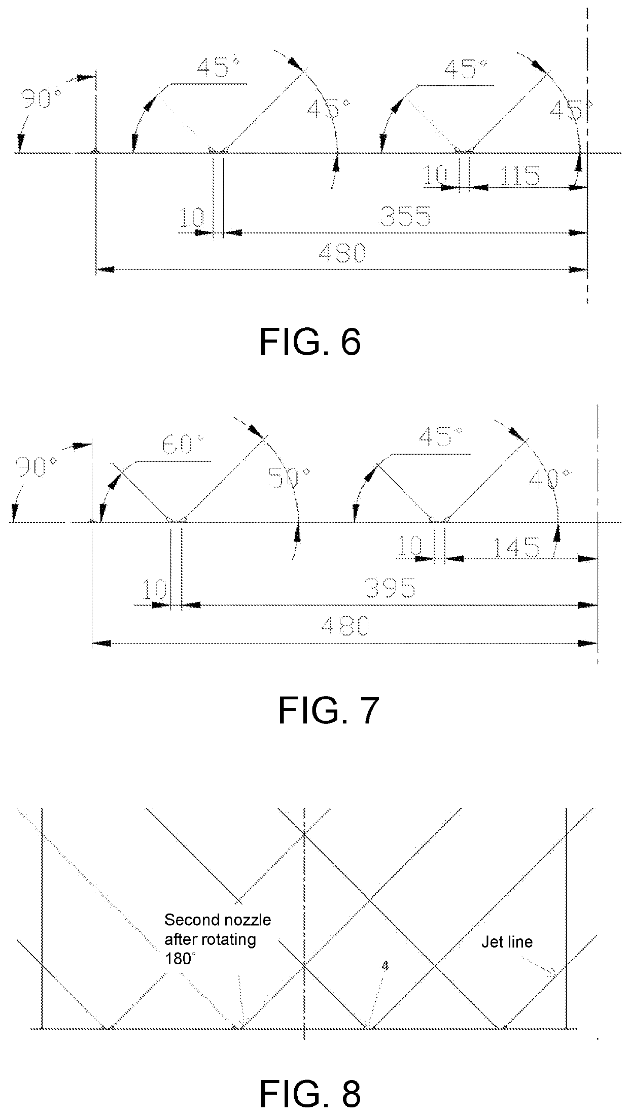
The present disclosure discloses an abrasive water jet full-section cutting type cutter head and application devices. The cutter head includes a cutter head body and a rotor eccentrically arranged on a working surface of the cutter head body. The rotor revolves with the cutter head body and also rotates about its own axis. At least one first nozzle is arranged on an edge of a working surface of the rotor. At least one group of second nozzles and at least one third nozzle are arranged on the working surface of the cutter head body, and the second nozzles and the third nozzle cooperate during the rotation of the cutter head body and the rotor, then a material to be cut is cut into a plurality of concentric rings, and the first nozzle cuts off the ring material to form fragments.

Description

CROSS-REFERENCE TO RELATED APPLICATION[0001]This application claims the priority benefits of China application serial no. 202110362877.5, filed on Apr. 2, 2021 and China application serial no. 202110534073.9, filed on May 17, 2021. The entirety of the above-mentioned patent application is hereby incorporated by reference herein and made a part of this specification.FIELD OF THE INVENTION[0002]The present disclosure discloses an abrasive water jet full-section cutting type cutter head and application devices, belonging to the field of tunneling or building demolition.BACKGROUND OF THE INVENTION[0003]The statement herein only provides background art related to the present disclosure, and does not necessarily constitute the prior art.[0004]The inventor found, in the fields of hard rock tunneling or building demolition, mechanical methods are commonly used at present to implement tunneling or demolition. Their principle is to squeeze and chop materials with disc hobs. Therefore, tools a...

Claims


Application Information

Patent Timeline
Patent Type & Authority Applications(United States)
IPC IPC(8): B24C1/04B24C7/00
CPCB24C1/045B24C7/0007B24C5/04B24C9/00
Inventor LIU, DUNZHANG, YIFEIZHU, HONGTAOZHANG, WEIJIEHUANG, CHUANZHEN
Owner SHANDONG UNIV
Learn More