
Membrane structure, transducer device and method of producing a membrane structure

a transducer device and membrane technology, applied in the direction of diaphragm construction, electrostatic transducer, semiconductor, etc., can solve the problems of gas significantly affecting the compliance of the membrane, limiting the sensitivity of the system, and compressing the gas within the volum

Pending Publication Date: 2022-10-13
AMS INT
View PDF0 Cites 0 Cited by
  • Summary
  • Abstract
  • Description
  • Claims
  • Application Information

AI Technical Summary

Benefits of technology

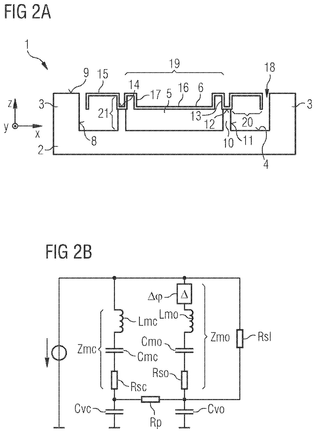
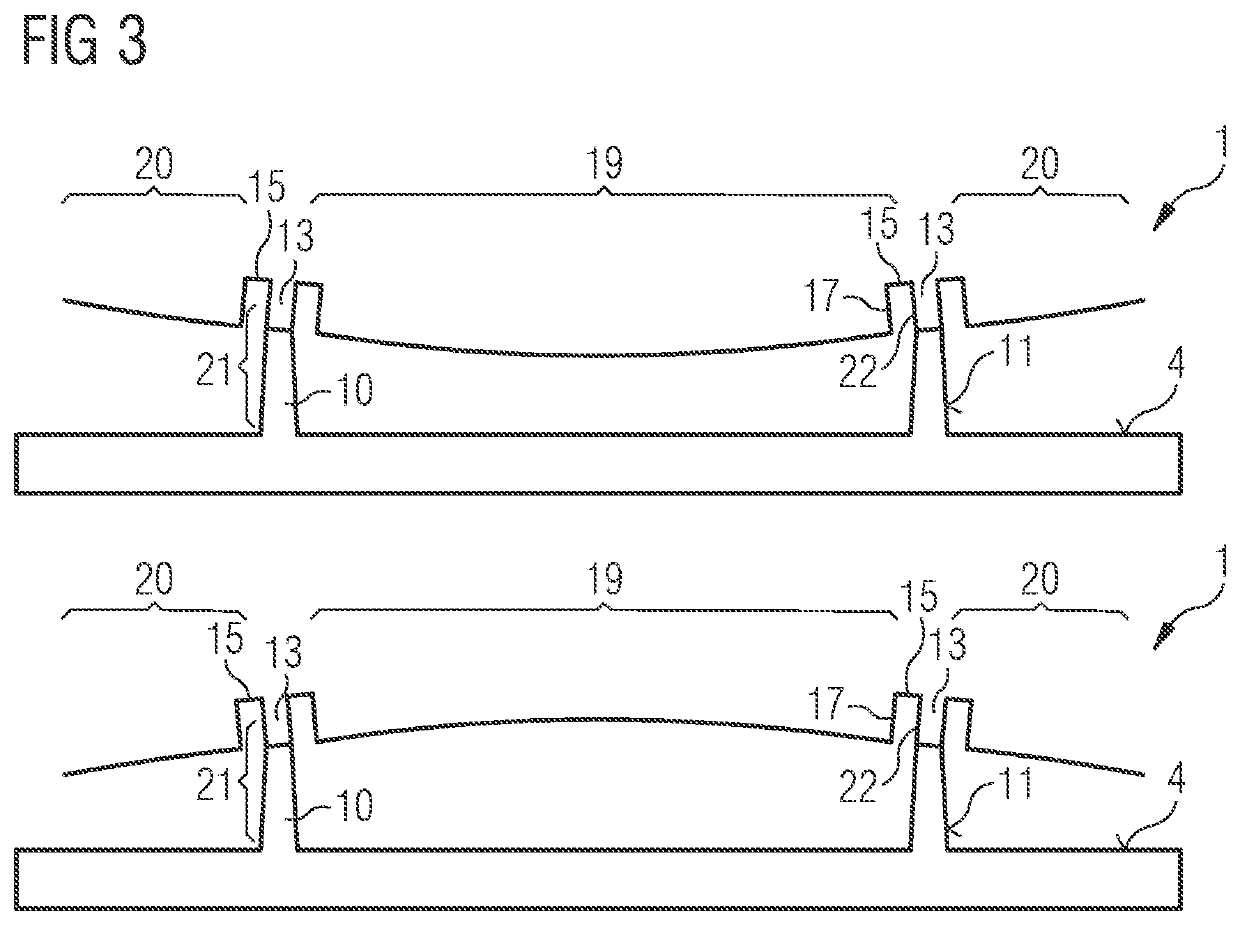
The patent describes a technique called mechanical phase shifters that improve the performance of membrane structures used in various applications such as sound devices or microphones. These shifters enable a small change in the volume of the back-space underneath the membrane, which reduces gas compression and increases system compliance. By arranging several shifters at specific locations, the compliance can be maximized. Additionally, by forming an opening in the substrate, access to the membrane can be provided and the volume of the space between the membrane and substrate can be increased, improving sensitivity and signal-to-noise ratio for optical reading of membrane displacement.

Problems solved by technology

However, the volume reduction under the membrane leads to a compression of the gas within the volume.
Such a compression of gas significantly affects the compliance of the membrane, in particular in miniaturized systems.
This means that for conventional membrane structures the back-volume, beside the membrane stiffness, limits the sensitivity of the system.

Method used


Image

  • Membrane structure, transducer device and method of producing a membrane structure
  • Membrane structure, transducer device and method of producing a membrane structure
  • Membrane structure, transducer device and method of producing a membrane structure

Examples


Embodiment Construction

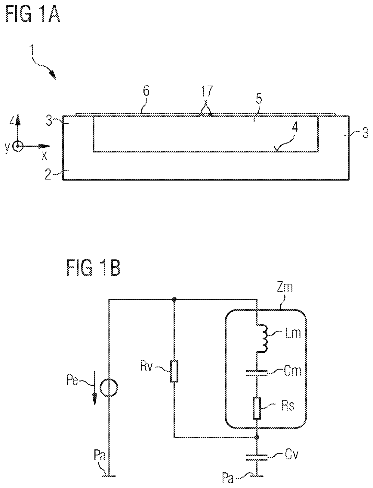
[0073]In FIG. 1a a cross-section of an example of a membrane structure 1, which is no embodiment, is shown. The membrane structure 1 is arranged in a conventional way. The membrane structure 1 comprises a substrate 2. An enclosing wall 3 is arranged at a main surface 4 of the substrate 2. The enclosing wall 3 surrounds a back-volume 5 in lateral directions x, y, where lateral directions run parallel to a main plane of extension of the substrate 2.

[0074]The membrane structure 1 further comprises a thin-film structure 6 above the main surface 4 of the substrate 2 attached to the enclosing wall 3. This means that the thin-film structure 6 is in mechanical contact to the enclosing wall 3. The thin-film structure 6 is spaced from the substrate 2 in a vertical direction z, where the vertical direction z is perpendicular to the main plane of extension of the substrate 2. The thin-film structure 6 spans the back-volume 5. This means that the back-volume 5 is enclosed by the substrate 2, the...


PUM

PropertyMeasurementUnit
heightaaaaaaaaaa
heightaaaaaaaaaa
heightaaaaaaaaaa

Abstract

A membrane structure comprises a substrate having a main surface and a rear surface. A plurality of pillars are arranged on the main surface of the substrate and have a support area facing away from the main surface of the substrate. A thin-film structure is arranged above the main surface of the substrate and the pillars, wherein the thin-film structure comprises a plurality of raised portions that are spaced further from the substrate than at least one lower portion of the thin film structure. The raised portions each comprise at least one protruding portion, the protruding portions being hollow and having a bottom part and a sidewall and the protruding portions extending towards the substrate. The bottom part of each protruding portion is mechanically connected to the support area of one of the pillars, respectively. A back-volume is formed by the volume between the main surface of the substrate and the thin-film structure.

Description

CROSS-REFERENCE TO RELATED APPLICATIONS[0001]The present application is the national stage entry of International Patent Application No. PCT / EP2020 / 074365, filed on Sep. 1, 2020, and published as WO 2021 / 047962 A1 on Mar. 18, 2021, which claims the benefit of priority of European Patent Application No. 19197358.5, filed on Sep. 13, 2019, all of which are incorporated by reference herein in their entirety.FIELD OF THE INVENTION[0002]The present disclosure relates to a membrane structure, a transducer device and a method for producing a membrane structure.BACKGROUND OF THE INVENTION[0003]For membrane-based transducer devices the deflection of the membrane causes a volume change of the volume under the membrane. However, the volume reduction under the membrane leads to a compression of the gas within the volume. Such a compression of gas significantly affects the compliance of the membrane, in particular in miniaturized systems. The compressed gas exerts a restoring force on the membra...

Claims


Application Information

Patent Timeline
Patent Type & Authority Applications(United States)
IPC IPC(8): B81B3/00B81C1/00H04R23/00
CPCB81B3/007B81C1/00158H04R23/008B81B2201/0257B81B2203/0127H04R2201/003H04R7/12H04R31/003H04R19/005
Inventor HEEB, PETERMÜLLER, MICHELLESTOJANOVIC, GORAN
Owner AMS INT
Learn More