There are drawbacks to this, in that, the resonant frequency point of the piezoelectric transformer is dependent on external variables including time, temperature, output load, and other variables.
These variables cause the optimum
power output of the transformer to degrade as frequency shifts unless the driving frequency can be continually corrected.
If a
driving circuit is unable to track the resonant frequency, the piezoelectric transformer will not be operated most effectively.
Changes in the resonant frequency due to aging, temperature, load variation, and other factors are not easily compensated for using this method.
One
advantage to this method is that a wider operating bandwidth is gained, however, this approach reduces efficiency and adds relatively large and expensive
reactive components.
This method does, however, have some practical disadvantages in operation.
Oftentimes, it is impractical or impossible to adequately filter or suppress these
modes sufficiently to assure that the self-oscillating circuit will always start and maintain its operation at the target resonant frequency.
Input drive
harmonics may be rejected by the high-Q transformer thereby reducing drive efficiency.
Another undesirable
scenario would be if the input drive
harmonics excited spurious
modes in the transformer which would be difficult to suppress.
Power
amplifier drivers typically produce a continuous sinewave drive
signal which sacrifices efficiency for low
harmonic content.
Another drawback to power
amplifier drivers is that they have difficulty driving large
capacitance values.
Still another option is to use switched totem-pole half-bridge drivers, but they also have limitations.
PWM drive
harmonics, like their switched totem-pole bridge drive cousins, sacrifice drive efficiency because of their significant
harmonic content.
PWM drives may also excite spurious vibrational
modes in the piezoelectric transformer.
Linear regulators are quite inefficient in this application, so switching regulators are generally preferred.
Unfortunately, switching regulators add their own inefficiency to that of the piezoelectric transformer and the associated drivers.
Another drawback to switching regulators is that they may also require at least one low-loss power
inductor and at least one low ESR output filtering
capacitor in addition to the switching
regulator controller and the associated power switches.
This has the disadvantages attributed to the use of switching regulators as described above.
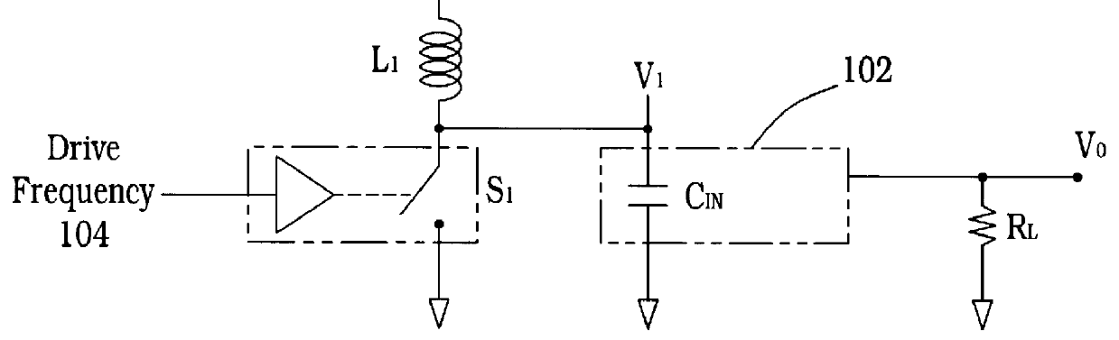
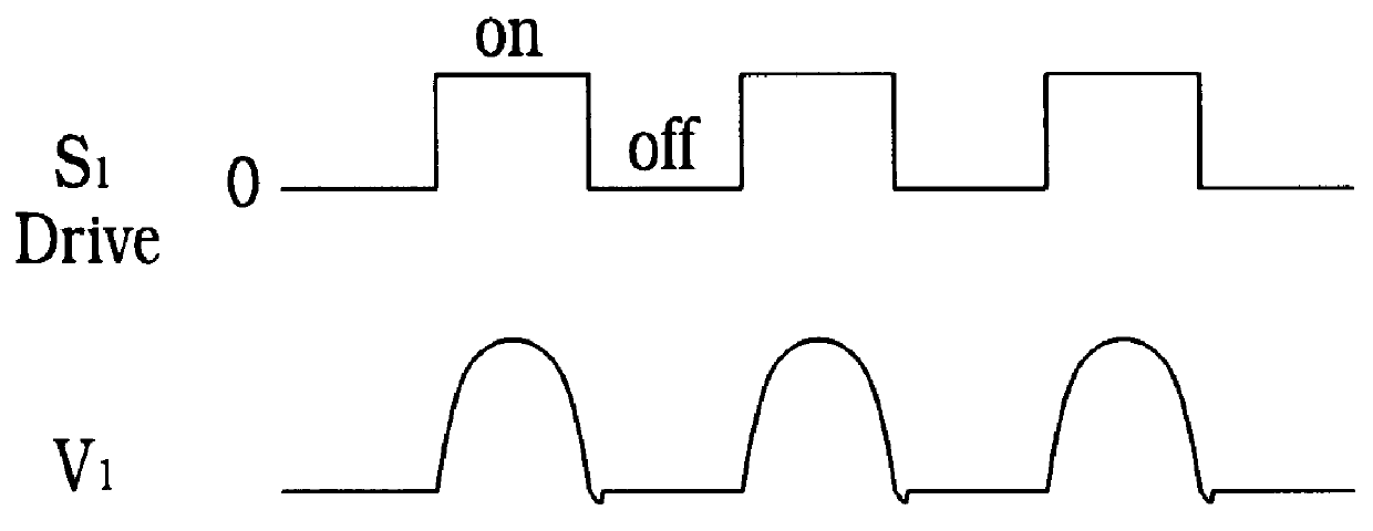
When S.sub.1 is enabled and the next resonant ZVS cycle begins, the
voltage on C.sub.IN will be shorted by S.sub.1, resulting in a large surge current in C.sub.IN and S.sub.1, and in dissipative losses which reduce efficiency.
If the disable
signal occurs while S.sub.1 is closed and current is flowing in L.sub.1, opening S.sub.1 will cause a large dI / dT through L.sub.1 which will, in turn, produce a large and potentially damaging
voltage spike across S.sub.1.
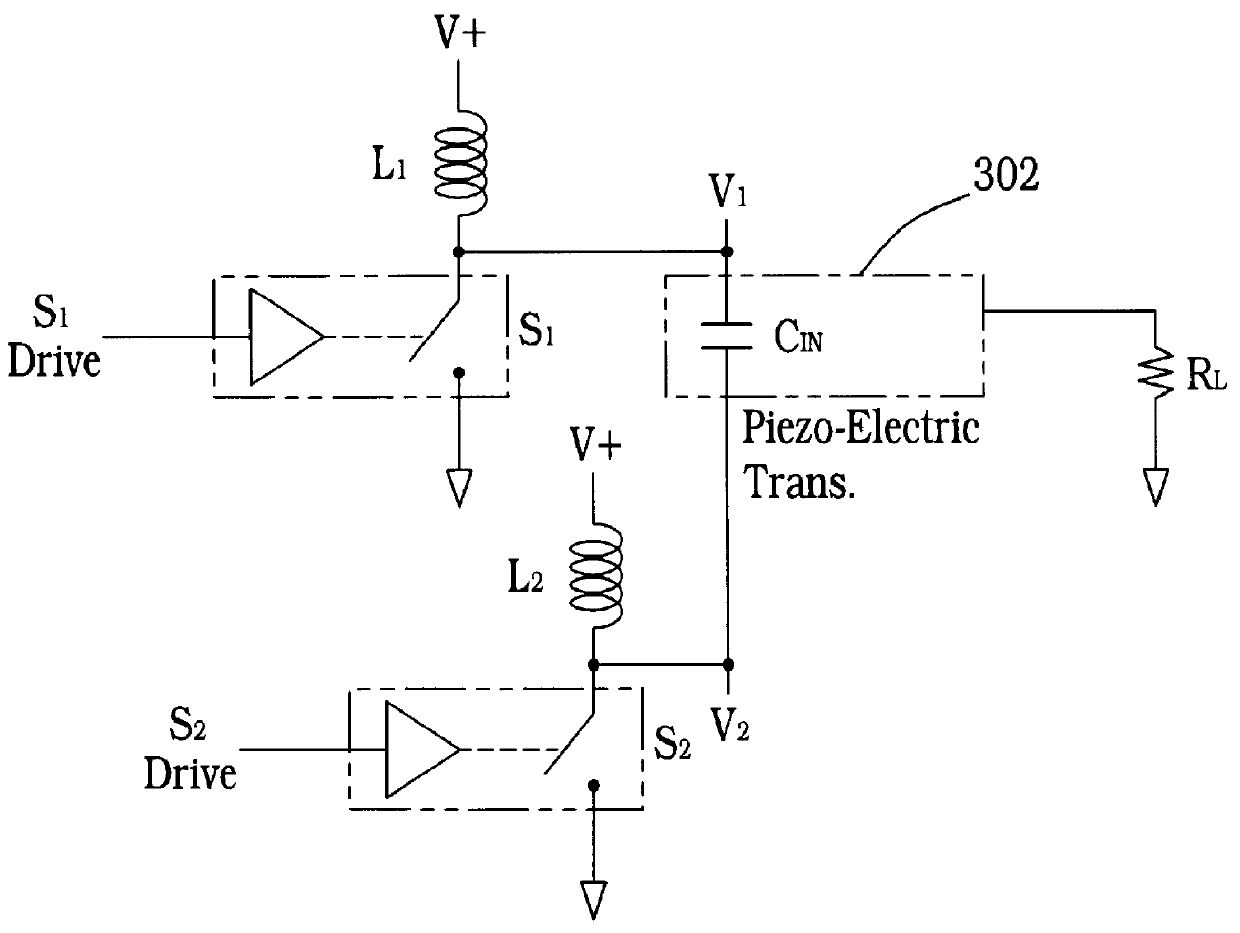
Another undesirable effect caused by prior art
pulse frequency modulation regulation involves the high-Q mechanical resonant characteristics of the piezoelectric transformer.
This mode of operation can dissipate the
resonant energy stored in the piezoelectric transformer and also cause an undesirable shift in the resonant frequency of the transformer.
These undesirable effects are repeated each time the resonant drive circuit is cycled by the PWM disable
signal.

