Method for charging refrigerant blend

Inactive Publication Date: 2000-02-01
DAIKIN IND LTD
View PDF8 Cites 27 Cited by
  • Summary
  • Abstract
  • Description
  • Claims
  • Application Information

AI Technical Summary

Benefits of technology

The inventors conducted extensive research on the method for charging a liquid gas so as to solve the problems associated with the composition change which occurs when a non-azeotropic mixture comprising 3 kinds of liquid gases having different boiling points and stored in a sealed vessel is transferred from liquid-containing vessel to another vessel.

Problems solved by technology

However, chlorofluorocarbons were found to be responsible for the destruction of the ozone layer when released into the stratosphere and eventually exert seriously adverse effects on the ecosystem including human on the earth.
This is caused by decrease of pressure and increase of the gaseous space derived from discharging, resulting in evaporation of low-boiling-point components from liquid phase.
The composition change, even of a few percent, causes a significant change in performances of refrigerant, and the change not only results in a decrease in capability and efficiency of the refrigerant, but also adversely affects safety of refrigerants such as flammability.

Method used


Image

  • Method for charging refrigerant blend
  • Method for charging refrigerant blend
  • Method for charging refrigerant blend

Examples


example 1

To a 10 liter sealed container, 9 kg of a non-azeotropic mixture of difluoromethane (HFC32), pentafluoroethane (HFC125) and 1,1,1,2-tetrafluoroethane (HFC134a) was charged in a weight ratio of 23.0 / 25.0 / 52.0. The container was placed into a thermostatic chamber and the temperature was maintained at 10.degree. C. or 40.degree. C. The temperature of 40.degree. C. was selected since the Pressurized Gas Control Law prohibits handling containers at a temperature over 40.degree. C., and the composition change increases as the temperature rises. Therefore data obtained at a temperature of 40.degree. C. are considered as the severest in conditions.

The mixture from the liquid phase was then transferred to another empty container at a rate of 900 g / min by means of a pump. A portion of the charging gas was withdrawn through a sampling valve located on a charging pipe near the liquid phase and the composition was analyzed by gas chromatography. The results are shown in Table 1.

TABLE 1 _________...

example 2

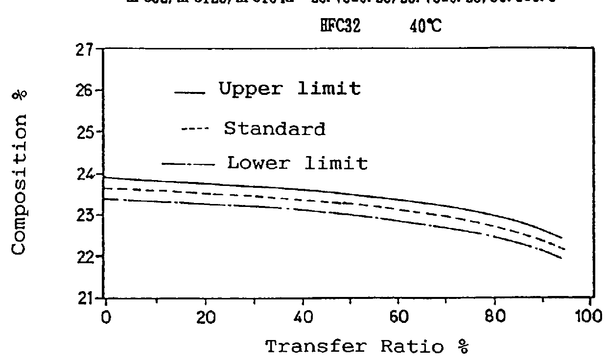
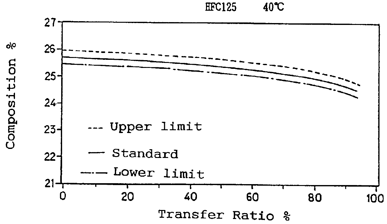
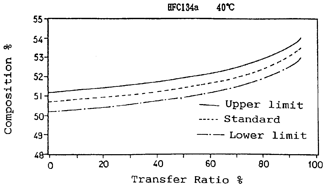
Transfer of charged gas was carried out by changing the proportions of components to the following; as for HFC32, composition mean value was changed to 23.75%, permissible lower limit and permissible upper limit in products were changed to 23.5% and 24.0%, respectively; as for HFC125, composition mean value (25.75%), lower limit (25.5%) and upper limit (26.0%), respectively; and as for HFC134a, composition mean value (50.5%), lower limit (50.0%) and upper limit (51.0%), respectively. The temperature of the thermostatic chamber is held at 40.degree. C., which is the severest temperature condition. The results are shown in Table 2.

TABLE 2 __________________________________________________________________________ Transferred Ratio and Analysis of the Collected Gas Composition according to the Present Invention Composition (wt %) Lower limit Upper limit Transfer Ratio (%) HFC32 HFC125 HFC134a HFC32 HFC125 HFC134a __________________________________________________________________________...


PUM


Abstract

The present invention provides A method for charging a refrigerant blend, when using as a refrigerant a non-azeotropic blend whose permissible range falls within 22 to 24% of difluoromethane, 23 to 27% of pentafluoroethane and 50 to 54% of 1,1,1,2-tetrafluoroethane, comprising adjusting a composition of non-azeotropic blend in a feeding container to the level of 23.5 to 24.0% of difluoromethane, 25.5 to 26.0% of pentafluoroethane and 50.0 to 51.0% of 1,1,1,2-tetrafluoroethane, discharging and transferring the non-azeotropic blend from the feeding container in liquid phase into another container in which a refrigerant is used so as to allow the composition change associated with the transfer to fall within the permissible range; and a method for producing a vapor compression refrigerating equipment.

Description

TECHNICAL FIELDThe present invention relates to a method for charging a non-azeotropic refrigerant blend comprising 22 to 24% of difluoromethane, 23 to 27% of pentafluoroethane and 50 to 54% of 1,1,1,2-tetrafluoroethane used as a working fluid for vapor compression refrigeration cycle, and to a method for producing a vapor compression refrigerator.BACKGROUND ARTVapor compression refrigeration cycle to perform cooling and heating of fluids by the use of state change of materials such as evaporation and condensation has found widespread use for applications such as an air-conditioner, refrigerator, hot-water supplier, etc. A variety of working fluids which are applied for the vapor compression refrigeration cycle, especially fluorocarbon refrigerants, have been developed and practically used. Among the fluids, HCFC22 (monochlorodifluoromethane) is widely used as a refrigerant in a heating and cooling system for air-conditioning.However, chlorofluorocarbons were found to be responsible...

Claims


Application Information

Patent Timeline
IPC IPC(8): C09K5/00C09K5/04
CPCC09K5/045C09K2205/22C09K2205/34
Inventor IDE, SATOSHITSUCHIYA, TATSUMI
Owner DAIKIN IND LTD
Why Eureka
Try Eureka