Multi-filar coil medical stent

Inactive Publication Date: 2000-02-01
MEDTRONIC INSTENT
View PDF18 Cites 448 Cited by
  • Summary
  • Abstract
  • Description
  • Claims
  • Application Information

AI Technical Summary

Benefits of technology

In one embodiment, both ends of each coil are attached in respective first and second common attachment junctions, and the resulting multi-filar stent forms an open coil stent having relatively even predetermined coil spacing between adjacent coil turns through the majority of the length of the stent between the first and last coil turns when the stent is released. In the constrained or restrained state, the stent is wound about the stent delivery catheter such that the stent diameter is reduced while the restrained stent length is substantially the same as the released stent len

Problems solved by technology

The dilatation of the occlusion, however, can form flaps, fissures and dissections which threaten re-closure of the dilated vessel or even perforations in the vessel wall after the balloon catheter is deflated and removed.
If the strain is too large, the material will experience plastic deformation to such an extent that the stent will not recover to the intended length and diameter dimensions following release and deployment.
Thus, the strain resistance and stent profile advantages of ribbon shaped wire cannot be realized using the loop defining the two legs and end cus

Method used


Image

  • Multi-filar coil medical stent
  • Multi-filar coil medical stent
  • Multi-filar coil medical stent

Examples


Embodiment Construction

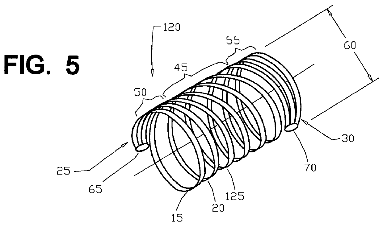
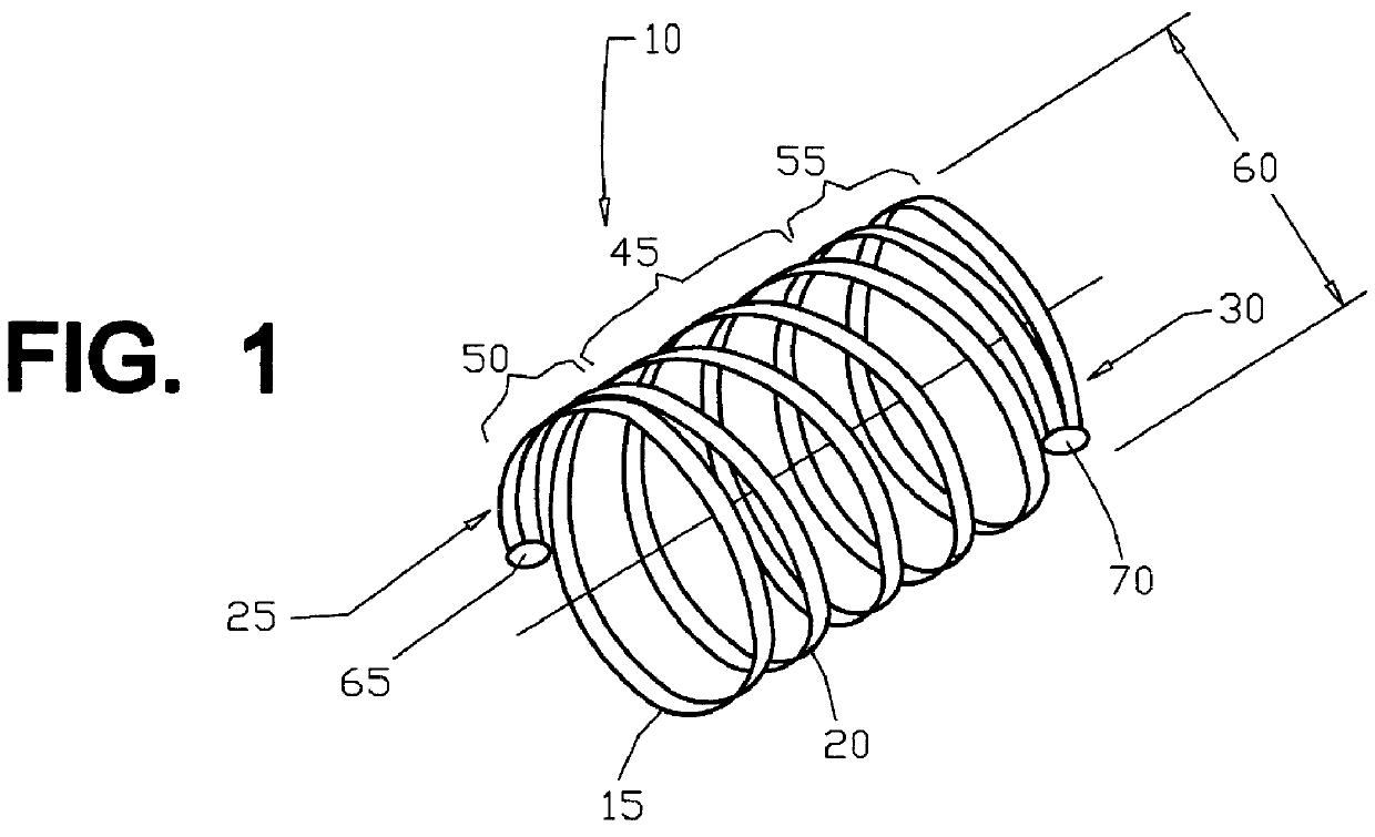
The present invention can be implemented in a multi-filar stent where each filar is a coil wound in substantially the same pitch through the majority of its length between the ends thereof, except for the final coil turn approaching an end, and the coils are interleaved with one another so that they do not cross over one another. The number of coils is preferably two or three or more, and bi-filar and tri-filar coil stents are described and depicted in the drawing figures as preferred embodiments of the present invention.

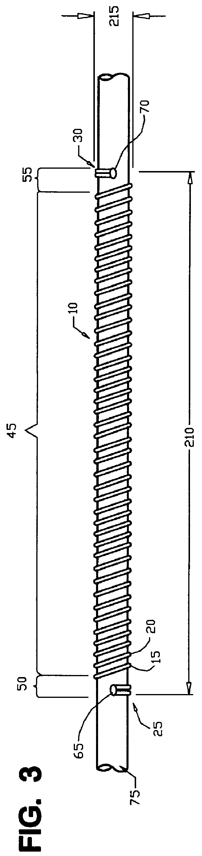
FIGS. 1-3 show a bi-filar open coil stent 10 formed in accordance with the present invention of first and second coils 15 and 20 which are attached together at attachment junctions of the coil ends to form first or proximal and second or distal, stent ends 25 and 30, respectively. The first and second coils 15 and 20 are preferably formed of a nickel-titanium, superelastic, shape memory, Nitinol.RTM. alloy having a rectangular or ribbon shaped cross-section.

In the r...


PUM


Abstract

Multi-filar, open and closed coil, tubular medical stents that are introduced to a site in a body lumen and released to expand at the site to provide a passageway through the stent lumen are disclosed. Each stent filar is a coil wound in substantially the same pitch through the majority of its length between the ends thereof. The coils are attached together at least at one coil end to form an end of the stent and wound in an interleaved manner such that the adjacent coils are substantially evenly spaced apart or in close contact in the released state and do not cross over one another. In one open coil stent embodiment, both ends of each coil are attached in respective first and second common attachment junctions, and the resulting coils have relatively even predetermined spacing between adjacent coil turns through the majority of the length of the stent between the first and last coil turns when the stent is released. Preferably, the first and second stent ends are formed by attaching the coil ends in common, and the stent ends are squared by decreasing the pitch of the first coil turn extending from the stent end such that the spacing of the stent end from the adjacent coil is reduced from the predetermined spacing. Additionally, multi-filar closed coil stent embodiments are disclosed having only one end of each coil attached in common and adjacent coil turns in substantial mutual and overlying contact in the restrained state during implantation and non-overlying contact in the released state. Preferably each common attachment junction of attached coil ends and each free coil end is formed into an enlarged stent end in at least one dimension for ease of attachment to and release from a stent delivery catheter. The common attachment junction can be snared or grasped by a stent retrieval system and retracted from the body lumen.

Description

The present invention relates to tubular stents introduced to a site in a body vessel, duct or tract or other body lumen to provide a passageway through the stent lumen, and more particularly to a multi-filar coil stent and method of fabrication and implantation thereof.Surgical and other medical procedures are often undertaken that involve delivery and implantation of tubular stents or grafts within organs, cavities or body lumens including blood vessels, urinary tracts, esophageal tracts, respiratory tracts, bile ducts, and colo-rectal tracts, that function to maintain a lumen for passage of body fluids or blood therethrough. Such stents are employed typically to widen or maintain the width of such a body lumen where an obstruction, injury or disease process threatens to close it.For example, percutaneous transluminal coronary angioplasty (PTCA) is used to increase the lumen diameter of a coronary artery partially or totally obstructed by a build-up of cholesterol fats or atherosc...

Claims


Application Information

Patent Timeline
IPC IPC(8): A61F2/06A61F2/84A61F2/88
CPCA61F2/88A61F2/95A61F2002/9511
Inventor THORUD, MICHAEL S.GUNDERSON, RICHARD C.
Owner MEDTRONIC INSTENT
Why Eureka
Try Eureka