Diffraction grating type band-pass filter and method of making the same

a band-pass filter and grating technology, applied in the field of band-pass filters, can solve the problems of large amount of transmission loss in the transmission wavelength band, difficult to narrow down the transmission wavelength band of the band-pass filter, and difficult to accurately separate only a specific wavelength with such a band-pass filter

Inactive Publication Date: 2000-02-01
SUMITOMO ELECTRIC IND LTD
View PDF3 Cites 29 Cited by
  • Summary
  • Abstract
  • Description
  • Claims
  • Application Information

AI Technical Summary

Benefits of technology

The boundary area formed between each periodic refractive index variable area and the zero area is effective in improving the transmission loss within the transmission wavelength band. It is due to the fact that, when the changing width of refractive index in the boundary area is rapidly changed from .DELTA.n to 0 or is repeatedly decreased or increased, the reflection caused by the diffraction grating becomes complicated, thereby enhancing the transmission loss-within the transmission wavelength band. In the present invention, such a complicated reflection would not occur, whereby the transmission loss can be suppressed.
Preferably, assuming that the length of each of the first and second boundary areas in their axial direction is L, the changing width of refractive index at a given position in the boundary area separated by a distance of x from a boundary position with respect to the zero area is expressed by .DELTA.n.multidot.f(x) using a given function f(x) which satisfies f(0)=0 and f(L)=1, the function f(x) monotonously and smoothly increasing from x=0 to L. This configuration is effective in suppressing the above-mentioned transmission loss.
Also, outside the first and second periodic refractive index variable areas, first and second end areas in which the changing width of refractive index monotonously changes between .DELTA.n and 0 may further be provided, respectively. It is assumed that, when the areas outside of the periodic refractive index variable areas are thus formed, reflections generated by combinations of the respective gratings forming the periodic refractive index variable areas and end areas cancel each other, thereby decreasing the reflection power generated outside the band.
When ultraviolet light irradiates a ultraviolet-sensitive optical waveguide, its refractive index can be changed according to the quantity of irradiated light. There has been known a method in which, by casting an interference fringe, the quantity of irradiated ultraviolet light is changed depending on places, so as to change refractive index locally, thereby forming a diffraction grating. In the method of the present invention, the scanning speed upon irradiating the ultraviolet beam is changed so as to control the quantity of irradiated light. As a consequence, the diffraction type band-pass filter in accordance with the present invention can be made easily.
Upon acceleration and deceleration in the scanning, the scanning speed may be accelerated and decelerated in conformity to a cos.sup.2 function, respectively. As a consequence, the changing width of refractive index can be controlled according to the scanning speed.
In this case, a diffraction grating type band-pass filter having a desired spectral characteristic can be obtained easily and securely.

Problems solved by technology

This kind of band-pass filter using chirp gratings, however, may yield a large amount of transmission loss in the transmission wavelength band, and it is difficult to narrow down its transmission wavelength band.
Accordingly, it is difficult for such a band-pass filter to accurately separate only a specific wavelength from a wide wavelength region.
By contrast, when two periodic refractive index variable areas are prepared independently of each other, it is quite difficult to accurately define the range of transmission wavelength band.

Method used


Image

  • Diffraction grating type band-pass filter and method of making the same
  • Diffraction grating type band-pass filter and method of making the same
  • Diffraction grating type band-pass filter and method of making the same

Examples


Embodiment Construction

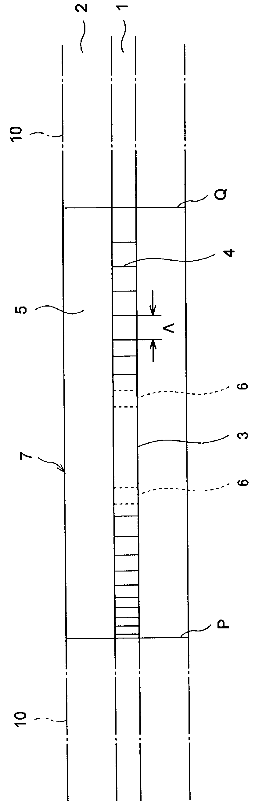
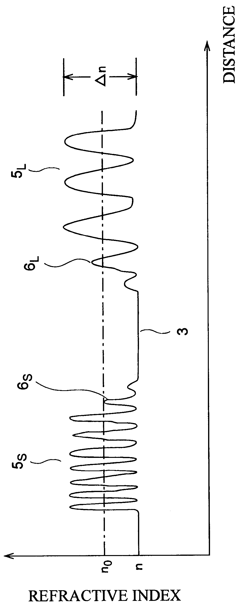
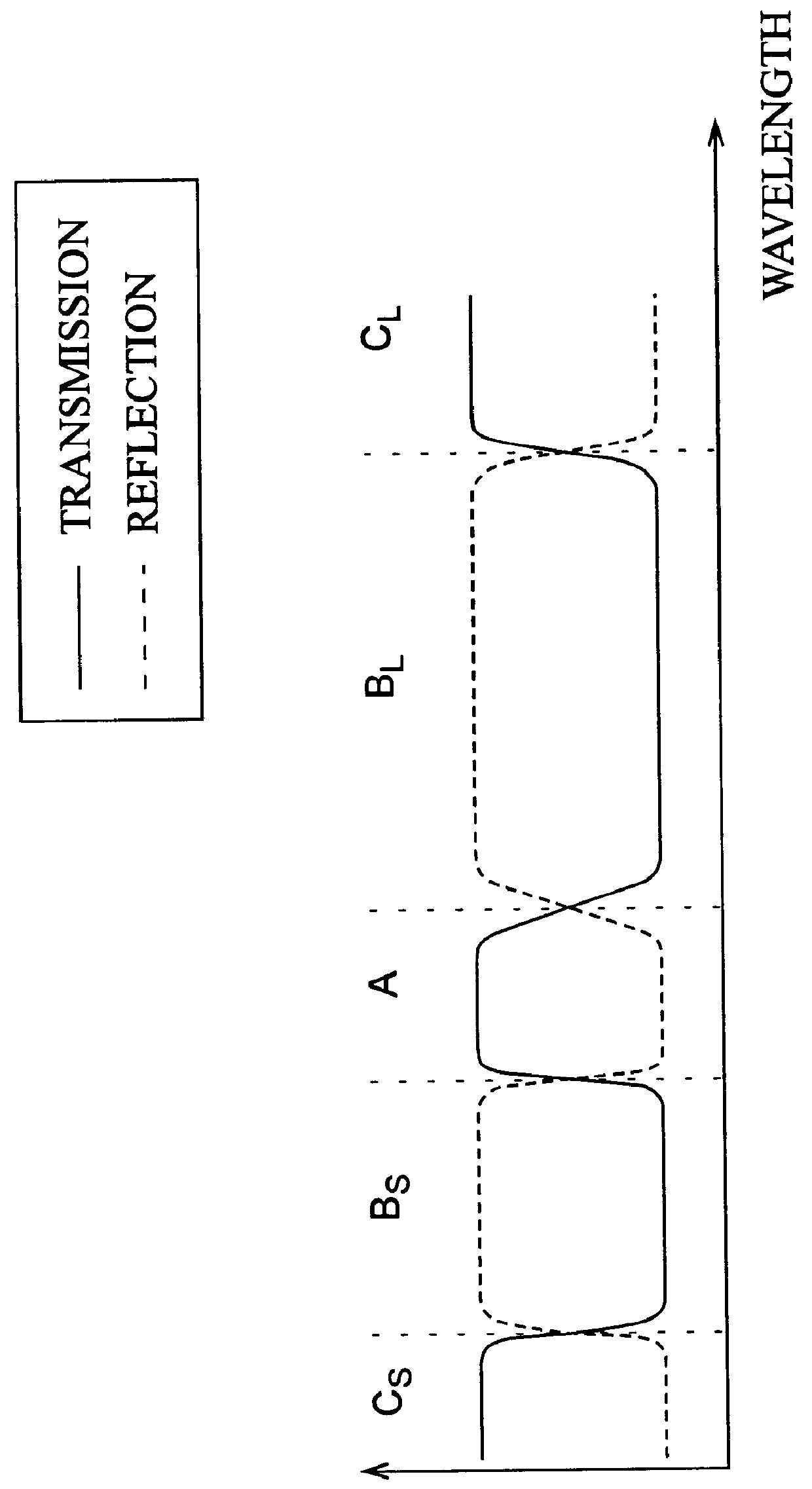
, irradiation was effected three times with different scanning speeds. Within the boundary areas 6, the scanning speed was linearly changed between that of the zero area 3 and that of the refractive index variable areas 5. FIGS. 9 and 10 show-the reflection and transmission characteristics of Examples A and B, respectively.

It can be seen that, as the ultraviolet light is repeatedly irradiated, the irradiation time becomes longer, thereby improving the reflection characteristic in the refractive index variable areas. As irradiation is repeated while these spectral characteristics are monitored, a filter having a predetermined reflection characteristic can be made easily.

FIG. 11A is a view showing a refractive index profile of a band-pass filter in this embodiment in the case where the fluctuation in refractive index in the boundary areas changes along a predetermined curve; FIG. 11B is an enlarged view showing the proximity of the boundary areas; and FIG. 11C is a graph showing wavel...


PUM


Abstract

A band-pass filter formed in an optical waveguide, provided with a diffraction grating group having a period LAMBDA of refractive index fluctuation changing in an axial direction with substantially a constant changing width DELTA n, comprises two periodic refractive index variable areas having periodes LAMBDA different from each other; a zero area, disposed therebetween, having substantially a constant refractive index; and boundary areas, disposed between the zero area and the respective periodic refractive index variable areas, in which the changing width of refractive index monotonously changes between 0 and DELTA n.

Description

1. Field of the InventionThe present invention relates to a band-pass filter using a diffraction grating formed in an optical waveguide, and a method of making the same.2. Related Background ArtOptical fiber-gratings have been known as a device used in optical fiber communication systems. In an optical fiber-grating, a light component having a specific wavelength is reflected according to a period between adjacent gratings, and light components having specific wavelengths are reflected according to respective periodes between other gratings. Accordingly, since light in a specific wavelength region can be effectively reflected, the optical fiber-grating has been used as a reflecting device.On the other hand, it has been known to combine optical fiber-gratings having different periods together so as to form a band-pass filter. An example of such a band-pass filter is disclosed in a paper titled "Fiber-grating transmission filters for use in an all-fiber demultiplexer" (OFC'94 Technica...

Claims


Application Information

Patent Timeline
Patent Type & Authority Patents(United States)
IPC IPC(8): G02B6/34G02B6/00G02B5/18G02B5/20G02B6/02
CPCG02B6/02085G02B6/29389
Inventor HARUMOTO, MICHIKOIWASHIMA, TORU
Owner SUMITOMO ELECTRIC IND LTD
Why Eureka
Try Eureka