Precise synchronization mechanism for SMP system buses using tagged snoop operations to avoid retries

a synchronization mechanism and snoop operation technology, applied in the field of computer systems, can solve the problems of not being able to determine from which processing unit an operation originated, not being able to determine if the outstanding operations in the snoop queue are valid, and not being able to determine what processing element is issuing the sync instruction,

Inactive Publication Date: 2000-02-22
IBM CORP
View PDF23 Cites 51 Cited by
  • Summary
  • Abstract
  • Description
  • Claims
  • Application Information

AI Technical Summary

Benefits of technology

It is therefore one object of the present invention to provide an improved method of synchronizing operations of different processors in a multi-processor computer system.
It is another object of the present invention to provide such a method which not only increases performance but further alleviates starvation and livelocks, and makes more efficient use of the interconnect bandwidth.

Problems solved by technology

However, in many current interconnect protocols (IBM's 60X bus protocol, for example), it is not possible to determine from which processing unit an operation originated.
In such a system, a processing unit must then retry every sync instruction if any operations are outstanding in its snoop queue, regardless of the origin of those operations, because it is impossible to determine if the outstanding operations in the snoop queue are from the processing unit issuing the sync.
Furthermore, in the prior art, it is also impossible to determine what processing element is issuing the sync instruction in the first place.
This limitation is inherently inefficient and can lead to starvation and livelocks.

Method used


Image

  • Precise synchronization mechanism for SMP system buses using tagged snoop operations to avoid retries
  • Precise synchronization mechanism for SMP system buses using tagged snoop operations to avoid retries

Examples


Embodiment Construction

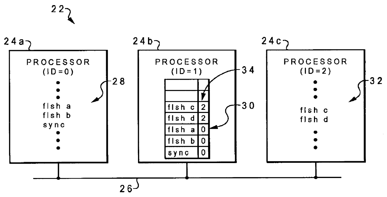
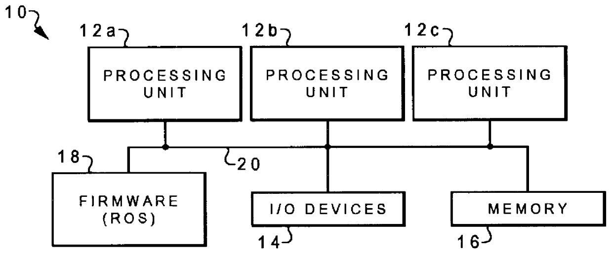
With reference now to the figures, and in particular with reference to FIG. 2, there is depicted one embodiment of a multi-processor computer system 22 according to the present invention. Computer system 22 includes three processing units 24a, 24b and 24c interconnected by a generalized interconnect or bus 26. The processing units can have various architectures, and in this illustrative embodiment would at least include a processor (having registers and execution units which carry out program and system instructions) and one or more caches. Computer system 22 may include other components, such as those discussed above regarding FIG. 1, as well as other new hardware components, or have a novel interconnection architecture for existing components, so the reference to FIG. 1 should not be construed in a limiting sense. Computer system 22 could also have many more than just three processing units.

In the present invention, a unique tag is assigned to each processor, that is transmitted w...


PUM


Abstract

A method of synchronizing an initiating processing unit in a multi-processor computer system with other processing units in the system, by assigning a unique tag for each processing unit, and issuing synchronization messages which include the unique tag of an initiating processing unit. The processing units each have a snoop queue for receiving snoop operations and corresponding tags associated with instructions issued by an initiating processing unit, and the processors examine their respective snoop queues to determine whether any snoop operation in those queues has a tag which is the unique tag of the initiating processing unit. A retry message is sent to the initiating processing unit from any of the other processing units which determine that a snoop operation in a snoop queue has a tag which is the unique tag of the initiating processing unit. In response to the retry message, the initiating processing unit re-issues the synchronization message, and the other processors re-examine their respective snoop queues, in response to the re-issuing of the synchronization message, to determine whether any snoop operation in those queues still has a tag which is the unique tag of the initiating processing unit.

Description

BACKGROUND OF THE INVENTION1. Field of the InventionThe present invention generally relates to computer systems and, more particularly, to a method of synchronizing instructions executed by different processors in a multi-processor computer system.2. Description of the Related ArtModern computing systems are often constructed from a number of processing elements and a main memory, connected by a generalized interconnect. The basic structure of a conventional multi-processor computer system 10 is shown in FIG. 1. Computer system 10 has several processing units 12a, 12b, and 12c which are connected to various peripheral devices, including input / output (I / O) devices 14 (such as a display monitor, keyboard, and permanent storage device), memory device 16 (such as dynamic random-access memory or DRAM) that is used by the processing units to carry out program instructions, and firmware 18 whose primary purpose is to seek out and load an operating system from one of the peripherals (usuall...

Claims


Application Information

Patent Timeline
Patent Type & Authority Patents(United States)
IPC IPC(8): G06F9/46
CPCG06F9/52
Inventor ARIMILLI, RAVI KUMARDODSON, JOHN STEVENLEWIS, JERRY DONWILLIAMS, DEREK EDWARD
Owner IBM CORP
Why Eureka
Try Eureka