Blade pitch locking device for a main rotor of a rotary-wing aircraft

a technology for rotary-wing aircraft and main rotors, which is applied to propellers, water-acting propulsive elements, propellers, etc., can solve the problems of difficult to save space on the deck of a ship for an on-board helicopter, the risk of damaging the component parts of the rotor, and the danger of tilting for personnel in the vicinity of the helicopter, etc., to achieve simple, effective and low cost

Inactive Publication Date: 2000-03-07
EUROCOPTER
View PDF8 Cites 76 Cited by
  • Summary
  • Abstract
  • Description
  • Claims
  • Application Information

AI Technical Summary

Benefits of technology

An object of the invention is to remedy the above-mentioned drawbacks by providing a blade pitch locking device for the main rotor of a helicopter, which device is simple, effective, and of low cost.
Thus, all three servo-controls are locked and together they prevent any movement of the pitch links which therefore hold the swinging masses in an accurate pitch position.

Problems solved by technology

The main rotor of a rotary-wing aircraft, in particular a helicopter, is generally rather large, which makes it difficult to save space on a parking area, or on the deck of a ship for an on-board helicopter, or indeed when stored in a hangar.
Such tilting can be dangerous for personnel in the vicinity of the helicopter and for the corresponding blade retaining-and-hinge means which can be damaged.
Furthermore, gusts of wind or motion of the ship on which the helicopter is located can cause said swinging masses to move, thereby running the risk of damaging the component parts of the rotor, and this can also be dangerous for personnel.

Method used


Image

  • Blade pitch locking device for a main rotor of a rotary-wing aircraft
  • Blade pitch locking device for a main rotor of a rotary-wing aircraft
  • Blade pitch locking device for a main rotor of a rotary-wing aircraft

Examples


first embodiment

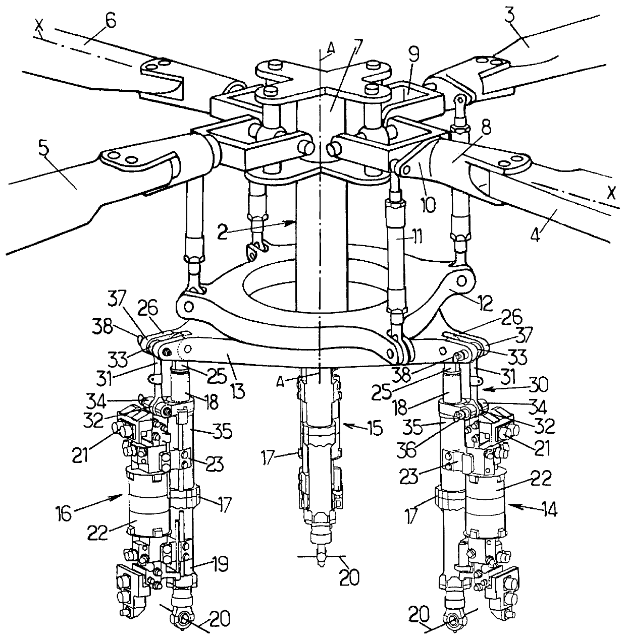
In the first embodiment as shown in FIG. 2, the second end 33 of the tooling link 31 is held vertically above the fork 34 in an extension 37 of the fork 26 holding the free end 25 of the rod 18. The second end 33 of the link 31 is fixed in the extension 37 by a ball pin 38.

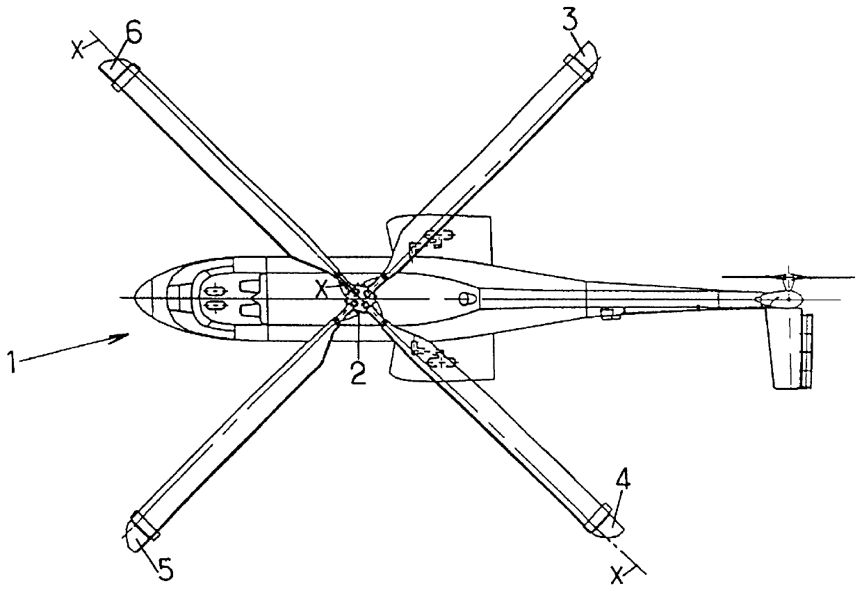
When it is desired to lock the blade pitch so as to fold back the blades 3 to 6, an operative puts the three tooling links 31 into place by placing their bottom ends 32 in the forks 34 and their top ends 33 in the extensions 37 of the forks 26. It then suffices to prevent these ends from moving relative to the forks by inserting the ball pins 36 and 38. The free ends 25 of the rods 18 of the servo-controls 14 to 16 are thus immobilized relative to the bodies 17 of the servocontrols. This makes it possible to immobilize the non-rotary plate 13 and thus to immobilize the cyclic swash plate mechanism 12, 13, thereby ensuring that blade pitch is fixed by means of the pitch links.

second embodiment

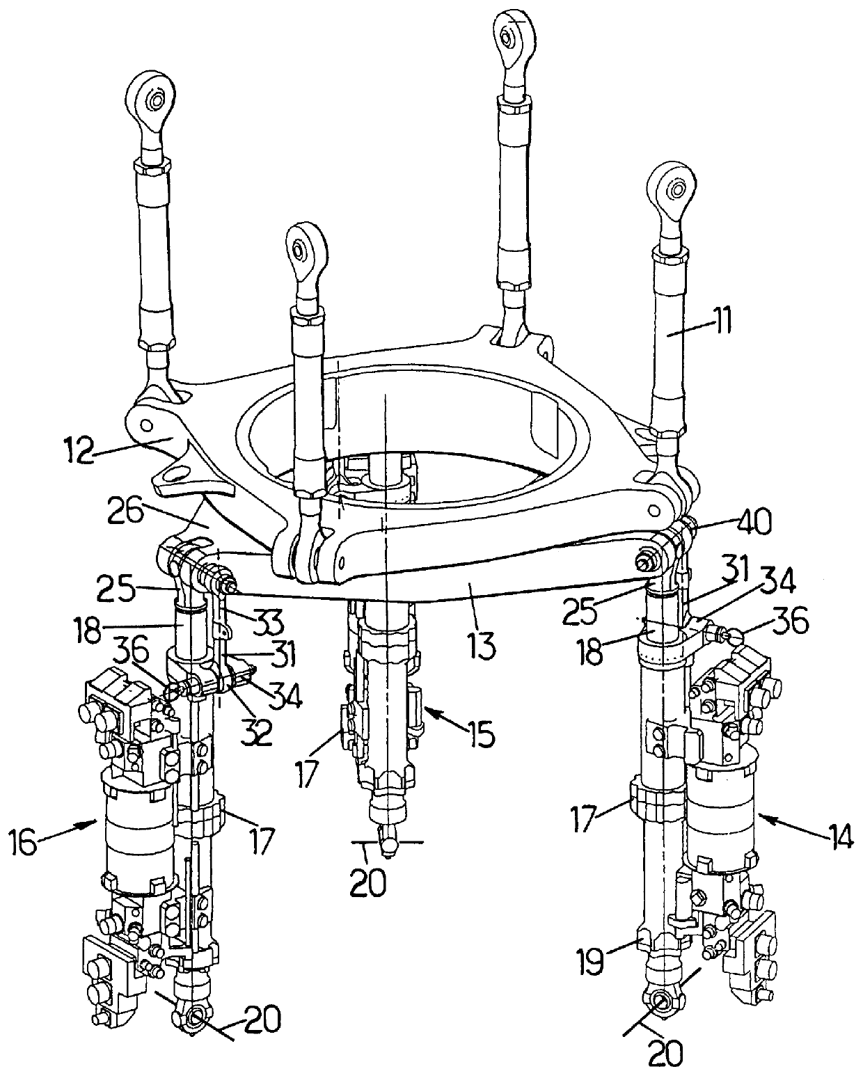
In the device of the present invention, as shown in FIGS. 3 and 4, the free end 25 of the rod 18 of each servo-control 14 to 16 is still held in the fork 26 carried by the non-rotary plate 13, with this being done by a bolt 40.

The fork 34 for holding the bottom end 32 of the tooling link 31 is situated in this example vertically below one of the ends 41 of the bolt 40. In order to hold the second end 33 of the tooling link 31 stationary in order to lock blade pitch, this second end 33 is engaged onto the end 41 of the bolt 40 and it is held in position by screwing a nut 42 onto the free end 41 of the bolt 40.

third embodiment

The third embodiment in FIG. 5 differs from the second embodiment shown in FIGS. 3 and 4 solely in that the nut 42 is not fitted to the end 41 of the bolt 40. The end 41 of the bolt 40 in this embodiment has a bearing surface 44 of tolerance suitable for accurately immobilizing the second end 33 of the tooling link 31. When locking blade pitch, the second end 33 of the link 31 is initially immobilized on the end 41 of the bolt 40, and then the first end 32 of the link is immobilized in its fork 34 by means of the ball pin 36.

As a safety measure, the presence of the tooling links 31 is signalled by a streamer (not shown) designed to be fixed to a streamer-fastening ring 45 provided on each of the links 31.

In a variant, the tooling links 31 can be permanently carried by the servo-controls 14 to 16. The first end 32 of each link 31 is then permanently fixed in the fork 34 carried by the body 17 of each servo-control. When not locking blade pitch, the link 31 is secured to the body 17, ...


PUM


Abstract

The present invention relates to a device for locking the pitch of the blades of a main rotor of a rotary-wing aircraft in which each blade is firstly rotated about an axis of rotation of the rotor by a rotor mast and is secondly constrained to pivot about a longitudinal pitch axis of the blade together with a pitch lever which is controlled by a pitch link connected to a rotary plate rotating with the rotor mast and belonging to a cyclic swash plate mechanism in which the rotary plate is rotatably mounted on a non-rotary plate capable of sliding axially along said rotor mast and of tilting in any direction relative to the rotor mast under the drive of at least three servo-controls each comprising a body fixed on a support secured to the aircraft and a rod having a free end secured to the non-rotary plate. The device includes immobilization means for holding the rod of each of the servo-controls relative to the corresponding body so as to lock the blades in a predetermined pitch position.

Description

The present invention relates to a device for locking the pitch of the blades of a main rotor of a rotary-wing aircraft in which each blade is firstly rotated about an axis of rotation of the rotor by a rotor mast and is secondly constrained to pivot about a longitudinal pitch axis of the blade together with a pitch lever which is controlled by a pitch link connected to a rotary plate rotating with the rotor mast and belonging to a cyclic swash plate mechanism in which the rotary plate is rotatably mounted on a non-rotary plate capable of sliding axially along said rotor mast and of tilting in any direction relative to the rotor mast under the drive of at least three servo-controls each comprising a body fixed on a support secured to the aircraft and a rod having a free end secured to the non-rotary plate.The main rotor of a rotary-wing aircraft, in particular a helicopter, is generally rather large, which makes it difficult to save space on a parking area, or on the deck of a ship ...

Claims


Application Information

Patent Timeline
Patent Type & Authority Patents(United States)
IPC IPC(8): B64C27/32B64C27/50
CPCB64C27/50
Inventor MONDET, JEAN JOSEPH HENRIMESTRE, GILBERT JEAN
Owner EUROCOPTER
Why Eureka
Try Eureka