Method of cleaning CVD cold-wall chamber and exhaust lines

a cold-wall chamber and exhaust line technology, applied in the direction of pressurized chemical processes, chemical/physical/physicochemical processes, coatings, etc., can solve the problems of affecting the heating efficiency of graphite parts, and forming unwanted deposits on the backside of the susceptor and preheat ring

Inactive Publication Date: 2000-03-28
APPLIED MATERIALS INC
View PDF17 Cites 140 Cited by
  • Summary
  • Abstract
  • Description
  • Claims
  • Application Information

AI Technical Summary

Problems solved by technology

If backside pressure or some other method of preventing backside deposition is not employed, unwanted deposits will form on the backside of the susceptor and preheat ring as well.
These unwanted films, if not removed, can impede the heating efficiency of the graphite parts.
However, deposits will form on the quartz domes which could interfere with radiant energy transmission from radiant lamp system 128.
Just like the deposits on other chamber components, these deposits could also flake or peel over time becoming sources of contamination and disrupt the process integrity.
Thus, the quartz components are usually coated to a much lesser degree than other chamber components and could be susceptible to damage from the chlorine radicals with energy levels beyond thermal reaction energy.
Although HCl removes silicon deposits from the chamber components, it does not remove them completely from the system.
Thus, any HCl that reaches the exhaust line will not remove the polymer but would likely contribute to polymer formation.

Method used


Image

  • Method of cleaning CVD cold-wall chamber and exhaust lines
  • Method of cleaning CVD cold-wall chamber and exhaust lines

Examples


Embodiment Construction

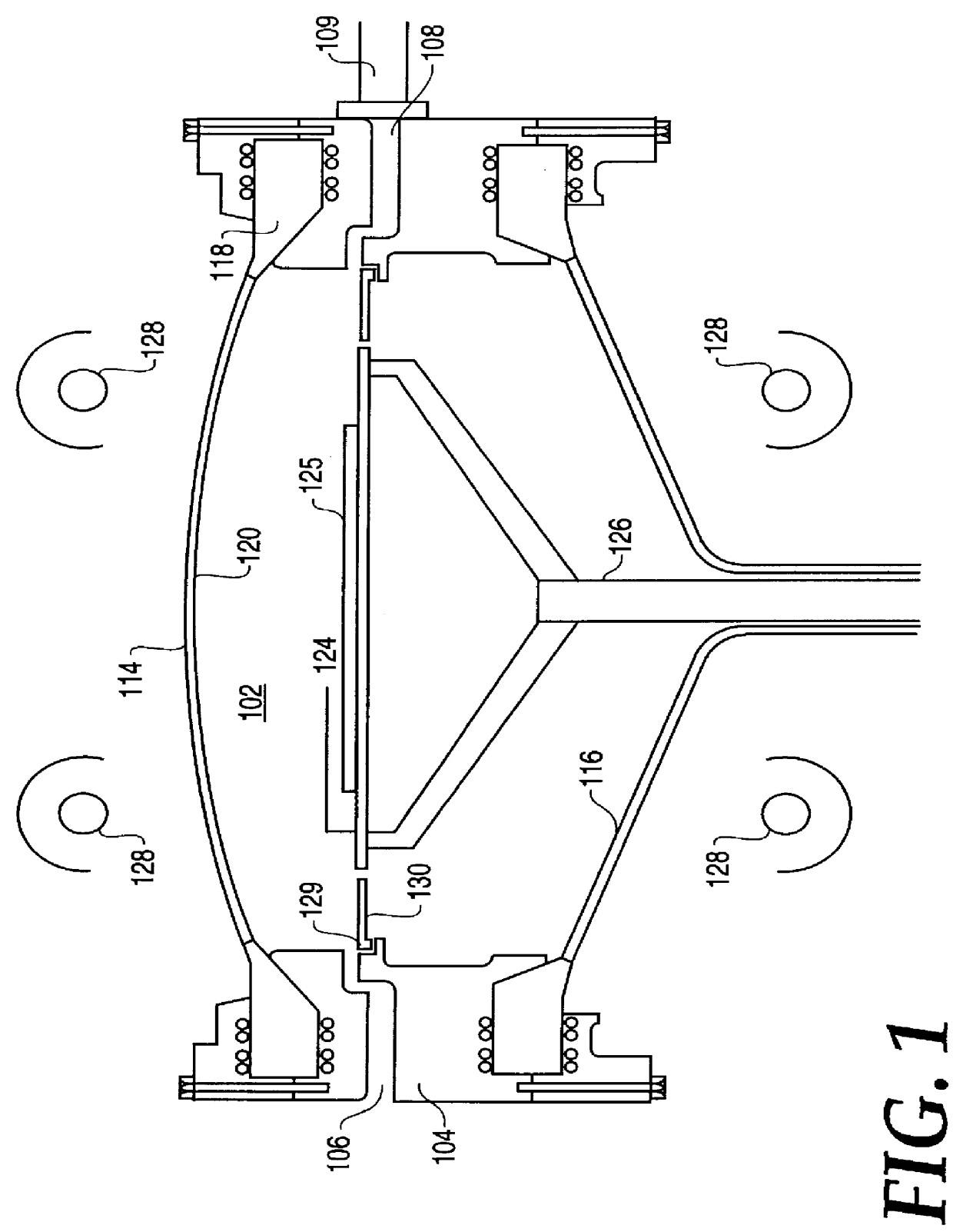
In the following description, numerous specific details such as silicon deposition techniques, quartz dome shape, lamp intensity and direction, collimator and reflector shape, chamber assembly and sealing methods have been omitted from the description in order not to preclude a thorough understanding of the present invention. Those skilled in the art will appreciate that the present invention may be practiced without these specific details. Although the present invention has been described for a single wafer cold-wall CVD reactor, variations in equipment and design can be made by one skilled in the art of CVD equipment and semiconductor wafer processing and are intended to be included herein.

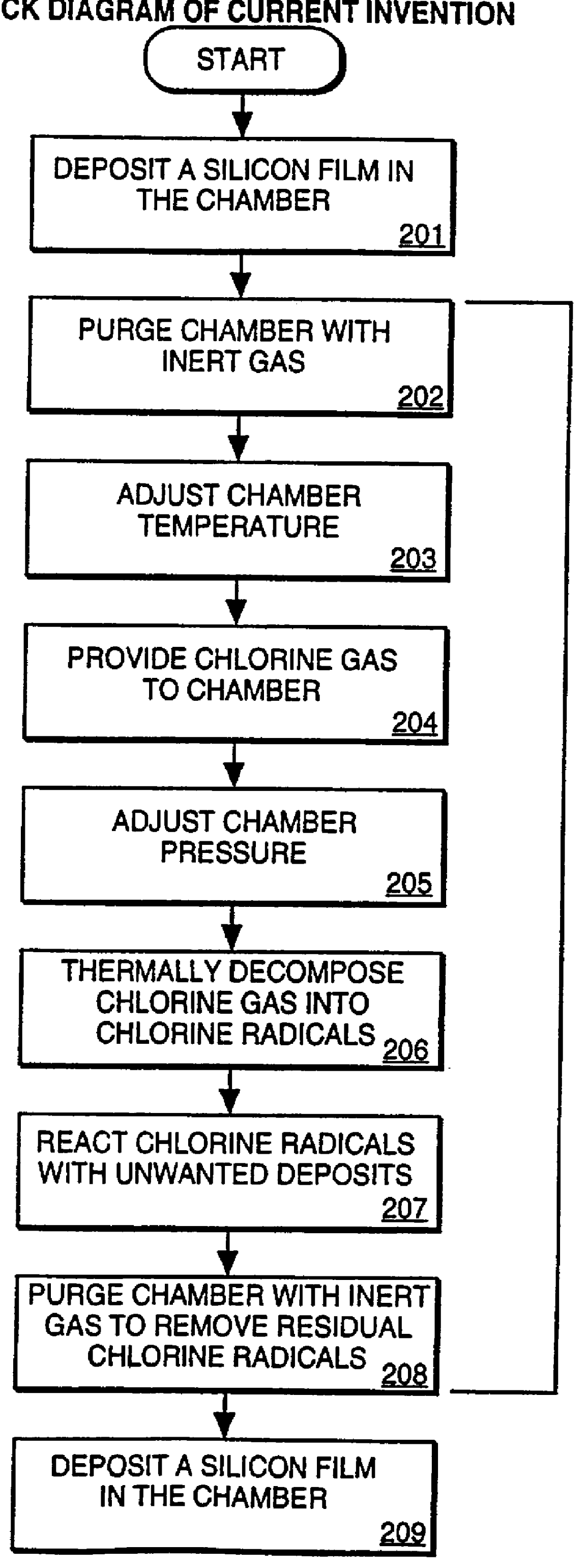
The present invention discloses an improved method of utilizing chlorine radicals from thermally decomposed chlorine gas (Cl.sub.2) for the removal of deposition by-products from the internal components and quartz walls of a cold-wall CVD chamber, and by-products from the exhaust lines.

The prese...


PUM

PropertyMeasurementUnit
temperatureaaaaaaaaaa
transfer temperatureaaaaaaaaaa

Abstract

A method of cleaning post deposition deposits from a processing chamber by providing a chlorine gas (Cl2), forming chlorine radicals and reacting the chlorine radicals with the deposits.

Description

1. Field of the InventionThe present invention relates to the field of methods of cleaning a deposition chamber, and more specifically, to a method of removing silicon deposition by-products from internal chamber components and chamber exhaust lines while minimizing the effect on quartz chamber components.2. Discussion of Related ArtIn epitaxial or polysilicon deposition processes, silicon is typically deposited onto the wafer using processes such as chemical vapor deposition (CVD). A cross-sectional view of a typical single wafer, cold-wall CVD apparatus is shown in FIG. 1. The Figure shows a thermal reactor 100 for processing semiconductor substrates comprising, a double-dome reactor vessel 114 principally made of quartz that defines a reactor chamber 102, upper 118 and lower 104 quartz chamber liners, gas inlet manifold 106, a gas exhaust manifold 108, exhaust line 109, a radiant heating system 128, a drive assembly 126, a susceptor 124, a wafer 125, and a preheat ring 130. Susce...

Claims


Application Information

Patent Timeline
Patent Type & Authority Patents(United States)
IPC IPC(8): C23C16/44B01J19/00B01J3/00H01L21/205
CPCC23C16/4405C23C16/30
Inventor COMITA, PAUL B.FORSTNER, HALI J. L.RANGANATHAN, REKHA
Owner APPLIED MATERIALS INC
Why Eureka
Try Eureka