

Gas sensor
a technology of gas sensor and sensor, applied in the direction of liquid/fluent solid measurement, electrochemical variables of materials, instruments, etc., can solve the problems of inability to perform measurement of combustion gas formed, sensitive to noise, and extremely small current based on objective nox in ordinary cases
- Summary
- Abstract
- Description
- Claims
- Application Information
AI Technical Summary
Benefits of technology
Problems solved by technology
Method used
Image

Examples
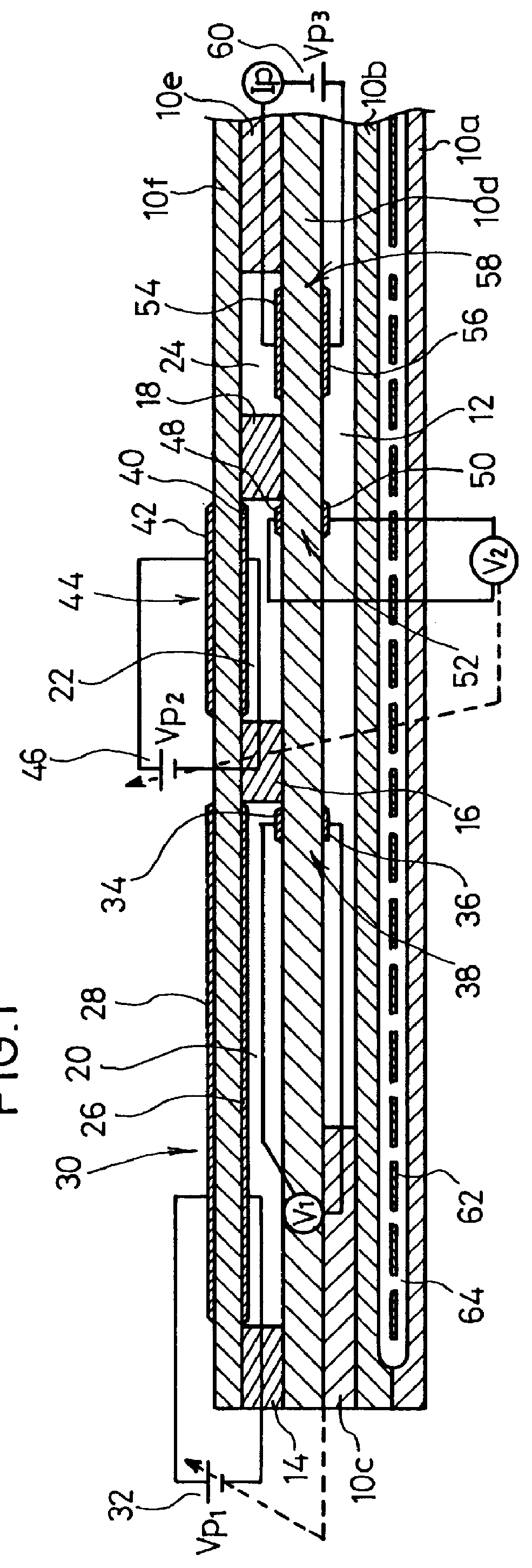
first embodiment
It is necessary for the gas sensor that the first and second inner pumping electrodes 26, 40 and the first and second measuring electrodes 34, 48 arranged in the first internal space 20 and the second internal space 22 do not cause reduction or decomposition of the measurement gas component (NOx) in the respective atmospheres at the ambient temperatures and at the controlled partial pressures of oxygen in the respective internal spaces 20, 22. Accordingly, an electrode metal such as Au and Ni having no or low reducing or decomposing ability for the measurement gas component is used for the first and second inner pumping electrodes 26, 40 and the first and second measuring electrodes 34, 48. It is advantageous to use a cermet electrode composed of the metal as described above, and a cermet electrode based on the use of an alloy obtained by adding a metal such as Au and Ni having no catalytic property to a noble metal such as Pt, Pd, and Rh.
The third inner pumping electrode 54 arrang...
second embodiment
Next, a gas sensor will be explained with reference to FIGS. 6 and 7. Components or parts corresponding to those shown in FIG. 1 are designated by the same reference numerals, duplicate explanation of which will be omitted.
As shown in FIG. 6, the gas sensor according to the second embodiment is constructed in approximately the same manner as the modified embodiment of the gas sensor according to the first embodiment. However, the former is different from the latter in that the second internal space 22 and the third internal space 24 are integrated into one combined internal space 80 composed of a flat space having an approximately rectangular planar configuration. Namely, the combined internal space 80 is comparted and formed by the lower surface of the second solid electrolyte layer 10f, the side surface of the second diffusion rate-determining section 16, side surfaces of the second spacer layer 10e, and the upper surface of the first solid electrolyte layer 10d.
A second inner pu...
third embodiment
Next, a gas sensor will be explained with reference to FIGS. 8 and 9. Components or parts corresponding to those shown in FIGS. 6 and 7 are designated by the same reference numerals, duplicate explanation of which will be omitted.
As shown in FIGS. 8 and 9, the gas sensor according to the third embodiment is constructed in approximately the same manner as the gas sensor according to the second embodiment. However, the former is different from the latter in that a third electrochemical pumping cell 58 is provided in place of the third electrochemical sensor cell 70.
Specifically, a second measuring electrode 48 of the second electrochemical sensor cell 52 is formed on a portion of the lower surface of the second solid electrolyte layer 10f for forming the combined internal space 80, the portion being separated from the second diffusion rate-determining section 16. A third inner pumping electrode 54 of the third electrochemical pumping cell 58 is formed at a position on the upper surfa...
PUM
| Property | Measurement | Unit |
|---|---|---|
| pressure | aaaaa | aaaaa |
| voltage | aaaaa | aaaaa |
| partial pressure | aaaaa | aaaaa |
Abstract
Description
Claims
Application Information