Integrated resonant tunneling diode based antenna

Inactive Publication Date: 2000-04-11
SANDIA
View PDF9 Cites 58 Cited by
  • Summary
  • Abstract
  • Description
  • Claims
  • Application Information

AI Technical Summary

Benefits of technology

FIG. 35 is a SEM cross section of a hole with a thickness:diameter ratio of about 3:1 a

Problems solved by technology

Presently, there is no practical direct solid-state means for power generation at millimeter or submillimeter wave frequencies.
The only solid-state approach for generating signals above 100 GHz is to use diode frequency multipliers which further red

Method used


Image

  • Integrated resonant tunneling diode based antenna
  • Integrated resonant tunneling diode based antenna
  • Integrated resonant tunneling diode based antenna

Examples


Embodiment Construction

)

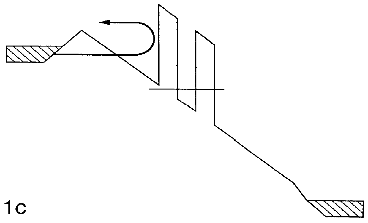
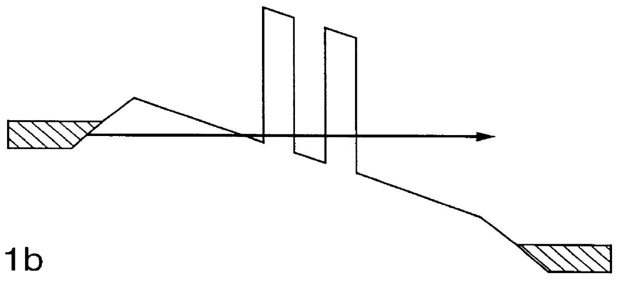
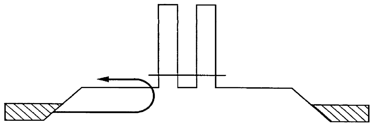
The present invention is of a quantum-transport device structure and fabrication process for millimeter-wave power generation and other applications. This structure realizes a power combination technique that couples a microstrip patch antenna to a resonant tunneling diode (RTD) array, forming a practical mm-wave power generator. The potential for remarkably high speed operation demonstrated by RTDs makes these devices suitable for coupling to small antennas with resonant frequencies at and beyond 100 GHz where efficient and inexpensive power generation has not yet been achieved.

A salient feature of these devices is a negative-differential-resistance (NDR) region which has been observed at room temperature in a number of material systems. The NDR region has been used as a basis for demonstrating high speed oscillations (712 GHz) and switching (.about.2 ps). These speeds have been among the fastest reported to date for any electronic device.

Several models were developed incorporatin...


PUM


Abstract

An antenna comprising a plurality of negative resistance devices and a method for making same comprising employing a removable standoff layer to form the gap between the microstrip antenna metal and the bottom contact layer.

Description

1. Field of the Invention (Technical Field)The present invention relates to resonant tunneling diode apparatuses and methods of manufacture and to millimeter-wave apparatuses and methods.2. Background ArtPresently, there is no practical direct solid-state means for power generation at millimeter or submillimeter wave frequencies. IMPATT (Impact Avalanche Transit Time) and Gunn diodes can only produce significant power levels (.gtoreq.10 mW) up to frequencies of about 100 GHz with a generation efficiency of less than 1%. The only solid-state approach for generating signals above 100 GHz is to use diode frequency multipliers which further reduces efficiency by more than a factor of five.Resonant tunneling diodes (RTDs) have demonstrated instabilities at frequencies in excess of 800 GHz. This makes them very promising for millimeter-wave oscillators. Unfortunately, in spite of the high current densities available in these devices, the RF power available is quite small. With current mat...

Claims


Application Information

Patent Timeline
IPC IPC(8): H01Q9/04H01Q21/00
CPCB82Y10/00H01Q21/0087H01Q9/0442
Inventor HIETALA, VINCENT M.TIGGERS, CHRIS P.PLUT, THOMAS A.
Owner SANDIA
Why Eureka
Try Eureka