Hyperspectral polarization profiler for remote sensing

a profiler and hyperspectral technology, applied in the field of hyperspectral polarization profiler for remote sensing, can solve the problems of high cost of fertilizers, inability to reproduce and accurately measure the polarization state of light, and inability to use wavefront methods

Inactive Publication Date: 2000-04-18
CONTAINERLESS RES
View PDF19 Cites 85 Cited by
  • Summary
  • Abstract
  • Description
  • Claims
  • Application Information

AI Technical Summary

Problems solved by technology

When a non-uniform wavefront occurs, reproducible and accurate measurements of the polarization state of light are not possible by a division of wavefront method.
Fertilizers are expensive, and the practice of excess fertiliz

Method used


Image

  • Hyperspectral polarization profiler for remote sensing
  • Hyperspectral polarization profiler for remote sensing
  • Hyperspectral polarization profiler for remote sensing

Examples


first embodiment

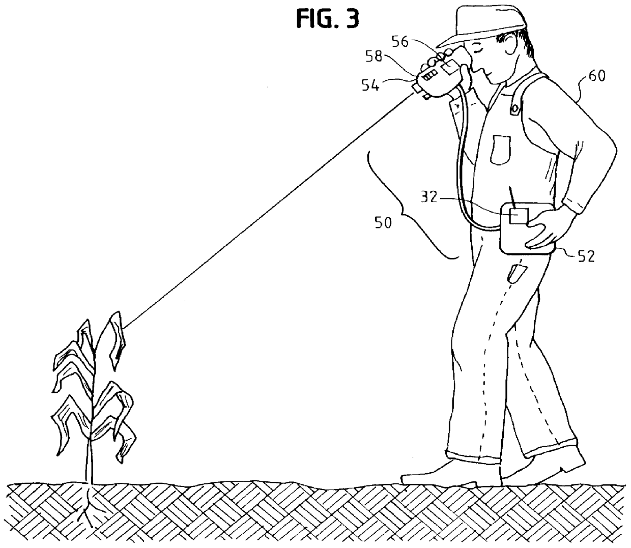
the present invention underwent field testing at a farm near Rossville, Ill. in July 1998. The field contained rows of corn divided into five areas with different levels of applied nitrogen fertilizer. There were two separate plantings, one in May (early) and one in June (late). Each planting consisted of twelve rows of plants about 750 feet in length. The spacing between the rows was thirty inches, and the spacing between the two groups was about eight feet.

The corn that was planted in May was on average about three feet tall. The corn planted in June was on average about 8-12 inches tall. The May corn had about 12-18 leaves per plant while the June corn had about 7 leaves per plant. The residual soil nitrogen level was estimated to be about 40 lbs / acre from the previous year's soybean crop. Both May and June groups had been dressed with differing amounts of added nitrogen, arranged in a non-sequential manner. The added fertilizer amounts were zero, 70, 150, 200, and 250 lbs / acre. ...


PUM


Abstract

A device to provide hyperspectral reflection spectrum, hyperspectral depolarization, and hyperspectral fluorescence spectrum data in a portable, remote sensing instrument. The device can provide a large range of remotely-sensed optical property data, presently only obtainable in laboratories, in a low-cost field instrument. Among its many uses, the present invention can be used by farmers as a tool for determining the nitrogen content of crops to optimize fertilizer laydown.

Description

This patent relates to a device and method for the remote sensing of characteristics of a target object. More specifically, this invention relates to a device and method that exploits the different optical properties of objects, such as depolarization upon reflection, to deduce structural information related to characteristics of an object.Theory of Light Scattering from an ObjectPolarimetry is the analysis of the polarization state of light. When polarized light (the "incident light") is directed onto an object, the depolarization upon reflection for the object can be directly measured. The depolarization which occurs upon reflection can be measured by splitting the reflected light into two orthogonally oriented states and calculating the signal ratios from two light sensitive detectors that view the orthogonally oriented light beams. The detectors, with separate polarization analyzers oriented perpendicular (P.sup.1) and parallel (p.sup.2) to the direction of polarization of the i...

Claims


Application Information

Patent Timeline
IPC IPC(8): A01C21/00G01N21/21G01N21/64G01J3/42G01J4/00G01J3/44
CPCG01J3/42G01J3/4406G01J4/00G01N21/21G01N21/64A01C21/007G01N2021/6417G01N2021/6419G01N2021/8466G01N2201/0221G01N2021/635
Inventor KRISHNAN, SHANKARHAMPTON, DANIEL SCOTTNORDINE, PAUL C.
Owner CONTAINERLESS RES
Why Eureka
Try Eureka