Chromatic dispersion compensator and chromatic dispersion compensating optical communication system

a technology of optical communication system and chromatic dispersion, which is applied in multiplex communication, instruments, optical elements, etc., can solve the problems of reducing transmission quality, affecting the insertion rate of chromatic fibers in the 1.55 .mu.m band, and affecting the insertion rate of chromatic fibers, so as to reduce the length of grating and reduce the loss of insertion. , the effect of reducing the length of the grating

Inactive Publication Date: 2000-04-25
SUMITOMO ELECTRIC IND LTD
View PDF8 Cites 56 Cited by
  • Summary
  • Abstract
  • Description
  • Claims
  • Application Information

AI Technical Summary

Benefits of technology

According to the chromatic dispersion compensator of the present invention, chromatic dispersion which cannot be compensated only by the dispersion compensating fiber is compensated by the chirped grating, so that not only chromatic dispersion of a transmission p

Problems solved by technology

If there arises chromatic dispersion in an optical fiber used as a transmission path in a optical digital transmission system, lowering of transmission quality is brought about.
Further, in the case where a 1.55 .mu.m-band optical fiber amplifier is used in the transmission path of a 1.3 .mu.m-band single mode fiber (1.3 SMF) having been already installed or in the transmission path of a very low loss pure silica core fiber, large positive chromatic dispersion of these fibers in the 1.55 .mu.m band

Method used


Image

  • Chromatic dispersion compensator and chromatic dispersion compensating optical communication system
  • Chromatic dispersion compensator and chromatic dispersion compensating optical communication system
  • Chromatic dispersion compensator and chromatic dispersion compensating optical communication system

Examples


first embodiment

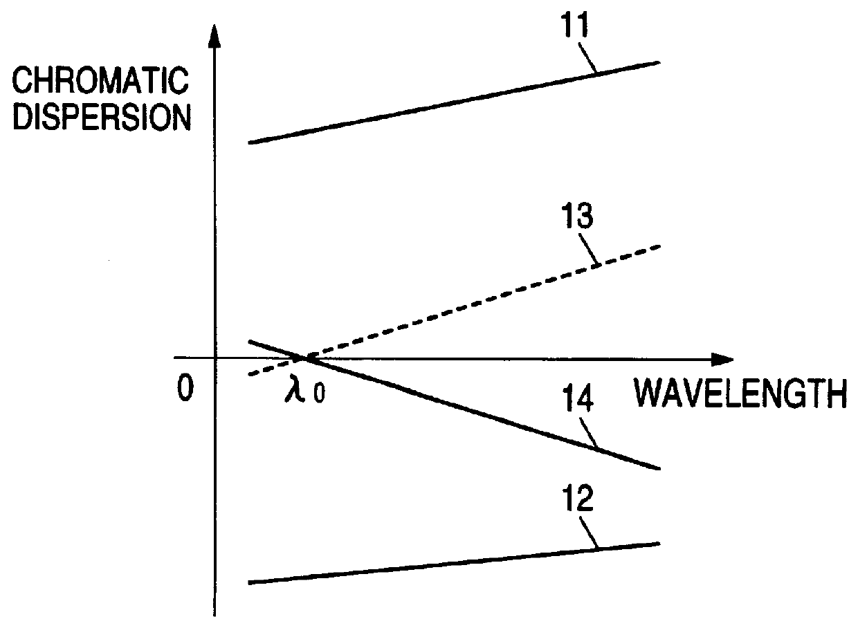
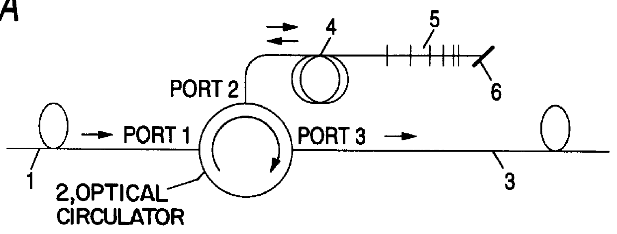
FIG. 2 is a graph for explaining the chromatic dispersion characteristic of the The horizontal axis represents wavelength of an optical signal, and the vertical axis represents chromatic dispersion. The reference numeral 11 represents chromatic dispersion characteristic of the transmission path; 12, round trip's chromatic dispersion characteristic of the dispersion compensating fiber; 13, characteristic obtained by adding the round trip's chromatic dispersion of the dispersion compensating fiber to the chromatic dispersion of the transmission path; and 14, chromatic dispersion characteristic of the chirped grating which has a negative dispersion slope characteristic. The dispersion compensating fiber 4 has negative chromatic dispersion so that the round trip's chromatic dispersion characteristic 12 thereof exhibits chromatic dispersion which is equal in absolute value to but has opposite sign to the chromatic dispersion exhibited by the chromatic dispersion characteristic 11 of the...

second embodiment

FIG. 5 is an explanatory view for explaining the present invention. In the drawing, elements the same as those in FIG. 1 are referenced correspondingly, and the description of those elements will be omitted. Reference numeral 31 represents an optical circulator; 32, Faraday rotator; and 33, a reflector. One variation of this embodiment is that the dispersion compensating fiber 4 is connected to the reflector 33 via the Faraday rotator 32, and the other one is that the chirped grating 5 is connected to the intermediate port of individual optical circulator 31. The Faraday rotator 32 changes the polarization direction of the reciprocating signal light.

The input transmission path 1 is connected to the first port which is an input port of the optical circulator 31. The output transmission path 3 is connected to a fourth port which is an output port thereof. The Faraday rotator 32 and the reflector 33 is sequentially connected so that the reflector 33 is connected to a second port which ...


PUM


Abstract

In a chromatic dispersion compensator, an optical signal directing unit such as an optical circulator or a directional coupler having a first, second, third and fourth ports. The optical signal directing unit directs an optical signal inputted from one of the ports to another port of the ports. A reflection-type compensator including a dispersion compensating fiber, a reflecting portion and changing unit for changing a polarization direction of a reciprocating signal light, in which the dispersion compensating fiber is connected to the reflecting portion via the changing unit. An input transmission path which is connected to the first port; and an output transmission path which is connected to the fourth port so that the signal light is outputted from the fourth port. The reflection-type compensating unit is connected to one of the second and third ports, and the chirped grating is connected to the other port.

Description

BACKGROUND OF THE INVENTION1. Field of the InventionThe present invention relates to a chromatic dispersion compensator for compensating chromatic dispersion in a transmission path of an optical fiber communication system and relates to a chromatic dispersion compensating optical communication system using such a chromatic dispersion compensator.2. Description of the Related ArtIf there arises chromatic dispersion in an optical fiber used as a transmission path in a optical digital transmission system, lowering of transmission quality is brought about. This is because chromatic dispersion and chirping produced by direct modulation of a semiconductor laser as a transmitter are coupled to generate waveform distortion. The degradation of transmission quality caused by waveform distortion becomes more remarkable as the bit rate increases. For example, in the case of 10 Gbps, it is necessary that the waveform distortion (spreading) is controlled to be sufficiently smaller than the time w...

Claims


Application Information

Patent Timeline
IPC IPC(8): H04B10/18
CPCH04B10/2519G02B6/29394H04B10/2569G02B6/2932G02B6/278
Inventor KOYANO, YASUSHISHIGEMATSU, MASAYUKI
Owner SUMITOMO ELECTRIC IND LTD
Why Eureka
Try Eureka