Non-linear asymmetrical audio amplifiers

a technology of symmetrical amplifiers and audio amplifiers, applied in the direction of amplifiers with field-effect devices, volume compression/expansion, semiconductor devices, etc., can solve the problems of amplifier overdrive, field-effect transistor amplifiers with biasing difficulties,

Inactive Publication Date: 2000-05-02
PRITCHARD ERIC K
View PDF5 Cites 25 Cited by
  • Summary
  • Abstract
  • Description
  • Claims
  • Application Information

AI Technical Summary

Problems solved by technology

The prior art field effect transistor amplifiers have biasing difficulties.
However, the variance in

Method used


Image

  • Non-linear asymmetrical audio amplifiers
  • Non-linear asymmetrical audio amplifiers
  • Non-linear asymmetrical audio amplifiers

Examples


embodiment

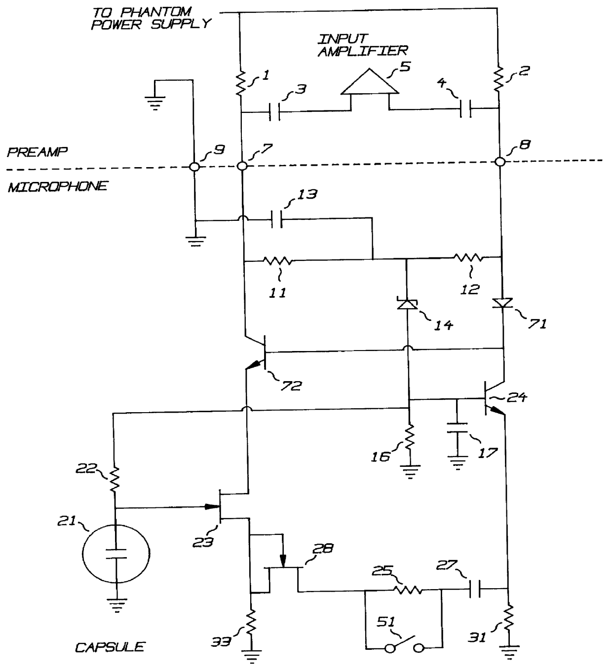
The First Microphone Embodiment

FIG. 3 shows the first microphone embodiment, a condenser microphone amplifier connected to a preamplifier having phantom power. The phantom power standard includes two resistors 1 and 2 which connect terminals 7 and 8 of the microphone connector to a power supply of approximately 50 volts. The signal is then extracted from the terminals with capacitors 3 and 4 which couple terminals 7 and 8 to the inputs of amplifier 5. Pin 9 provides a ground return for the phantom power.

The microphone amplifier has two resistors, 11 and 12, to receive the phantom power. They are connected together to provide operational power to the amplifier, ie. transistor bias currents. The DC bias at this junction is further lowered by zener 14 to provide bias for the differential amplifier. Any residual audio is filtered by capacitor 17. Resistor 16 ensures a minimum current in the zener 14.

The bias voltage is connected to the microphone capsule 21 through resistor 22. Resistor...


PUM


Abstract

Non-linear asymmetric amplifiers incorporate different non-linear characteristics in single ended or differential configurations to avoid cancellation of non-linear characteristics and to produce the harmonic structures of vacuum tubes. The operating currents of the asymmetrical devices are different to create a bias shift in the coupling capacitance between the asymmetrical devices.

Description

This invention relates to audio amplifiers and non-linear amplifiers, and more specifically, to capacitively coupled asymmetrical differential amplifiers with a capacitor bias that is altered by an asymmetrical means to produce a bias shift as a function of signal level.THE OBJECTS OF THIS INVENTIONAn object of this invention is an amplifier having a first and second non-linear means having fundamentally different non-linear characteristics which are capacitively coupled and having resistor means for setting and optionally adjusting the operating points of the non-linear means.An object of this invention is an asymmetrical differential amplifier having dissimilar technology transistors.A further object of this invention is a condenser microphone amplifier with optional filtering and proportional DC--DC converter for biasing the condenser capsule.FIG. 1 is a schematic of a basic single-ended amplifier having the biasing and limiting techniques of the present invention.FIG. 2 is a sch...

Claims


Application Information

Patent Timeline
IPC IPC(8): H03G7/00H03F1/30H03F3/181H03G7/06H03F1/32H03F3/185
CPCH03F1/306H03F1/3264H03G7/06H03F3/1855H03F1/3276
Inventor PRITCHARD, ERIC K.
Owner PRITCHARD ERIC K
Why Eureka
Try Eureka