Low power oscillator having fast start-up times

a low-power, oscillator technology, applied in the field of oscillators, can solve the problems of large bias resistors and load capacitors, weak amplifying inverters, and long start-up times,

Inactive Publication Date: 2000-05-02
MICROCHIP TECH INC
View PDF1 Cites 36 Cited by
  • Summary
  • Abstract
  • Description
  • Claims
  • Application Information

AI Technical Summary

Benefits of technology

will be apparent from the

Problems solved by technology

This creates a problem since the start-up times may be fairly long and unpredictable.
The bias resistor and the load capacitors are large and the amplifying inverter may be weak.
This causes considerable delay for the oscillator circuit to reach appropriate bias levels.
Once the amplifying inverter of the oscillator circuit is biased to its region of maximum gain, the amplifying

Method used


Image

  • Low power oscillator having fast start-up times
  • Low power oscillator having fast start-up times
  • Low power oscillator having fast start-up times

Examples


Embodiment Construction

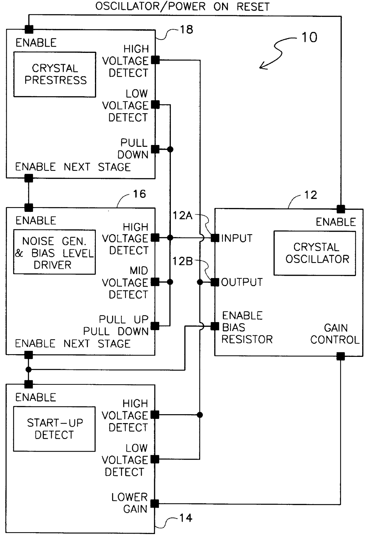
In accordance with one embodiment of the present invention, a low power oscillator having fast start-up times is disclosed. The oscillator has an oscillator circuit for generating a signal of a desired frequency. A prestress circuit is coupled to an input and to an output of the oscillator circuit for prestressing a piezoelectric resonator of the oscillator circuit to shorten start-up times of the oscillator circuit.

In accordance with another embodiment of the present invention, a low power oscillator having fast start-up times is disclosed. The low power fast starting oscillator uses an oscillator circuit having an input and an output for generating a signal of a desired frequency. A start-up detect circuit is coupled to the output of the oscillator circuit for detecting when the oscillator circuit has reached steady state operation and for generating a start-up circuit output signal which adjusts the gain of the oscillator circuit when steady state operation has been reached by th...


PUM


Abstract

A low power oscillator having fast start-up times. The low power fast starting oscillator uses an oscillator circuit having an input and an output for generating a signal of a desired frequency. A start-up detect circuit is coupled to the output of the oscillator circuit for detecting when the oscillator circuit has reached steady state operation and for generating a start-up circuit output signal which adjusts the gain of the oscillator circuit when steady state operation has been reached by the oscillator circuit. A noise generator is coupled to the input of the oscillator circuit and to the start-up detect circuit for inputting a noise pulse into the oscillator circuit. The noise pulse is used for biasing the input of the oscillator circuit to approximately an optimal bias voltage level. The noise generator is further used for sending an enable start-up detect signal to the start-up detect circuit to activate the start-up detect circuit. A prestress circuit is coupled to the input and to the output of the oscillator circuit for prestressing a piezoelectric resonator of the oscillator circuit to shorten start-up times of the oscillator circuit. The prestress circuit is further used for sending an enable noise generator signal to the noise generator to activate the noise generator.

Description

1. Field of the InventionThis invention relates generally to oscillators and, more specifically, to a piezoelectric based oscillator which consumes less power and which has faster start-up times than prior art oscillators.2. Description of the Prior ArtThe start-up time of an oscillator is defined as the time required for the oscillator to reach a steady state. Presently, for most oscillators, the start-up time can be several seconds depending on the crystal frequency and amplifier design of the oscillator. The start-up time may be even longer when the temperature of the device using the oscillator increases. This creates a problem since the start-up times may be fairly long and unpredictable.The reason for the delay is that when the oscillator circuit is powered up, the output of the amplifying inverter begins to bias the input through a bias resistor. The bias resistor and the load capacitors are large and the amplifying inverter may be weak. This causes considerable delay for the...

Claims


Application Information

Patent Timeline
IPC IPC(8): H03L3/00H03B5/00H03B5/06
CPCH03L3/00H03B5/06
Inventor PRADO, LOUIS A.
Owner MICROCHIP TECH INC
Why Eureka
Try Eureka