Object detecting apparatus

Inactive Publication Date: 2000-05-09
HONDA MOTOR CO LTD
View PDF5 Cites 56 Cited by
  • Summary
  • Abstract
  • Description
  • Claims
  • Application Information

AI Technical Summary

Problems solved by technology

Consequently, it is undesirable that a pedestrian bridge, a land bridge, a traffic sign, cat's eyes, or the like, which would not be an obstacle, is detected as an obstacle by mistake.
If the vertical width between upper and lower limits of the detection region is set to be narrow, however, there is a possibility that a pedestrian bridge, a land bridge, a traffic sign, cat's eyes, or the like, is detected by mistake because an original obstacle such as a vehicle running in front, or the like, cannot be detected when the vertical angle of the detection region changes in accordance with main factors such as accuracy in attachment of the object detecting apparatus to a vehicle body, nose up caused by sudden acceleration, nose dive caused by sudden braking, undulation of the road surface, loading condition, etc.

Method used


Image

  • Object detecting apparatus
  • Object detecting apparatus
  • Object detecting apparatus

Examples


first embodiment

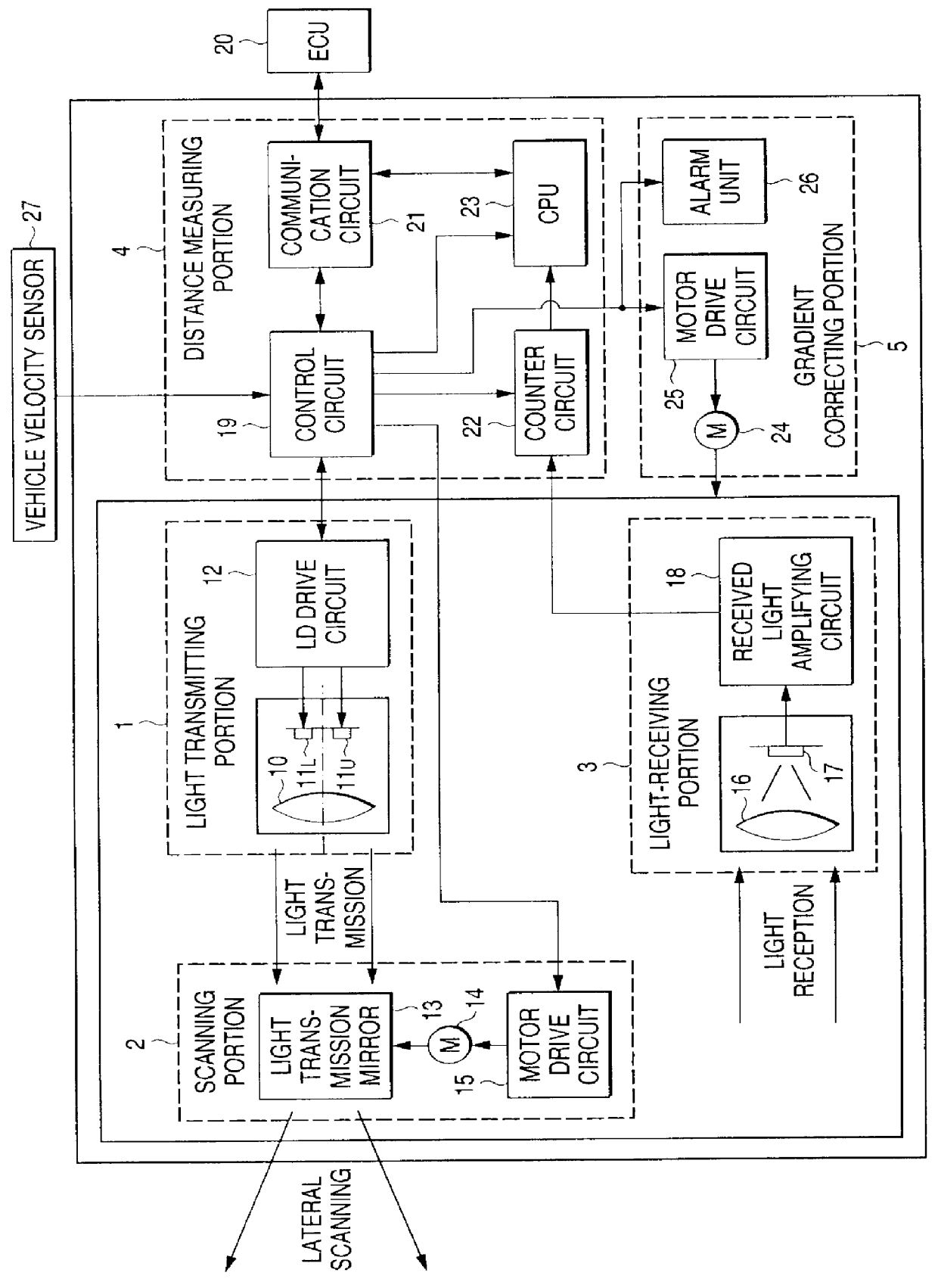
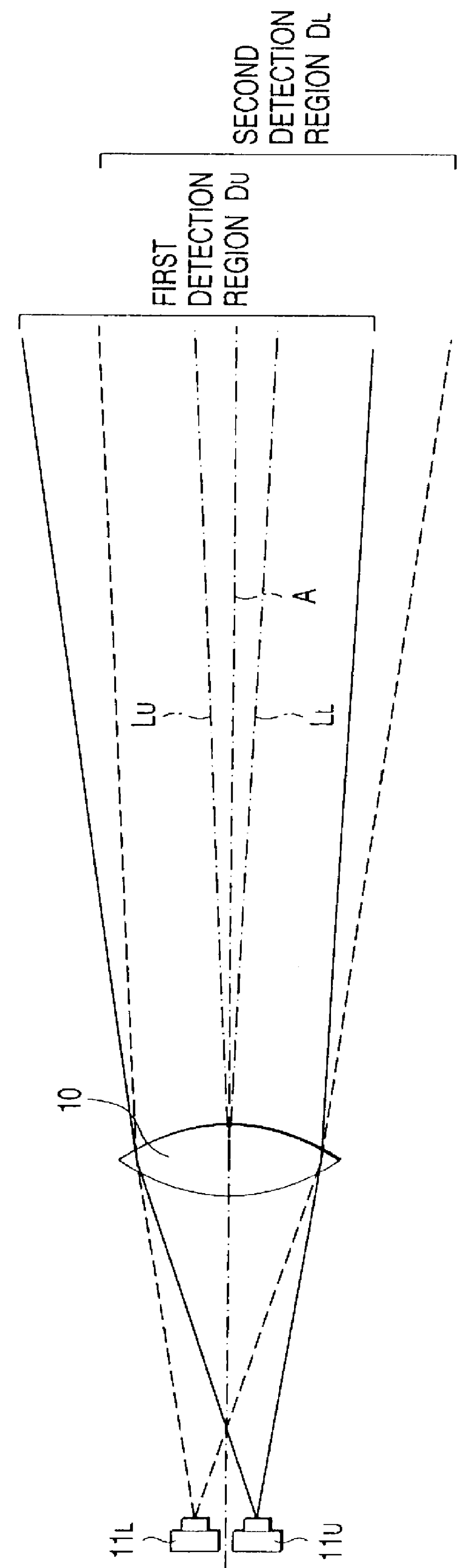
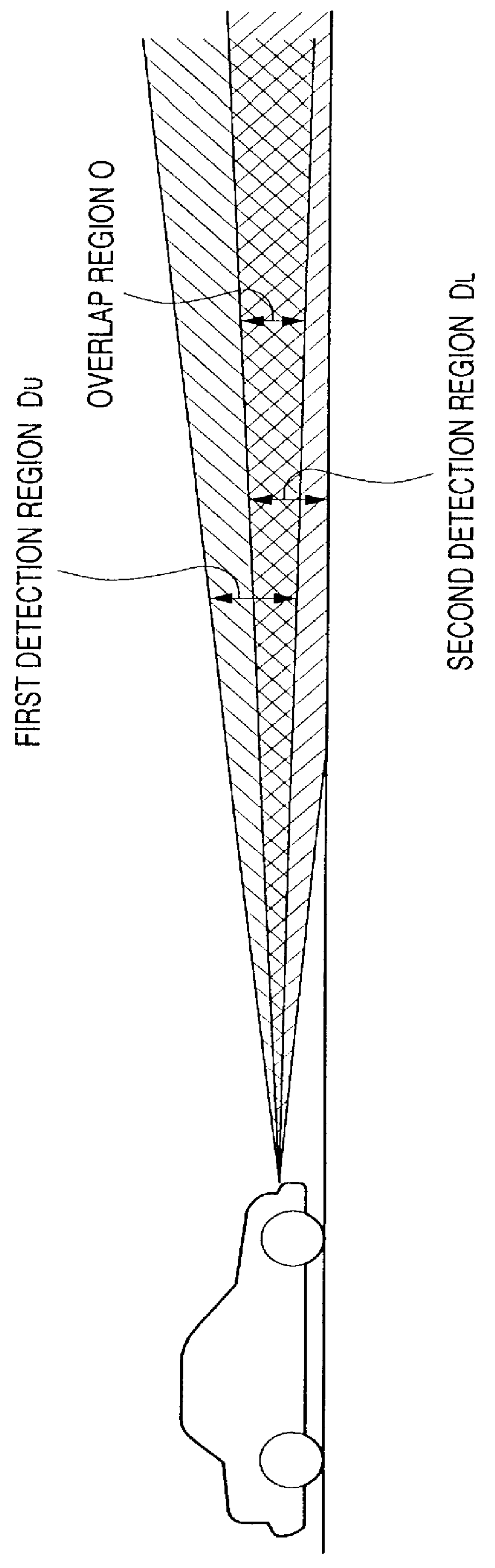
FIGS. 1 to 5 show the present invention. FIG. 1 is a block diagram of an object detecting apparatus. FIG. 2 is an enlarged view of the light transmitting portion. FIG. 3 is an explanatory view of the detection regions. FIG. 4 is a block diagram of the gradient correcting circuit. FIG. 5 is a flow chart for explaining the operation of the present invention.

As shown in FIG. 1, the object detecting apparatus of a vehicle for detecting the distance between the vehicle and another preceding vehicle is constituted by a light transmitting portion 1, a scanning portion 2, a light receiving portion 3, a distance measuring portion 4, and a gradient correcting portion 5. The light transmitting portion 1 is provided with a light-transmitting lens 10, a pair of upper and lower laser diodes 11.sub.U and 11.sub.L, and a laser diode drive circuit 12 for driving the laser diodes 11.sub.U and 11.sub.L. The scanning portion 2 is provided with a light-transmitting mirror 13 for reflecting laser beams e...

second embodiment

the present invention will be described below with reference to FIG. 6.

In the second embodiment, configuration is made such that a single laser beam is sent from the light transmitting portion 1 and reflected waves of the laser beam are received in the light receiving portion 3 side so that a pair of upper and lower detection regions, that is, first and second detection regions D.sub.U and D.sub.L are provided. A halfmirror 28 is disposed near to the focal point of the light-receiving lens 16 so as to be inclined at 45.degree. with respect to the optical axis A. Among reflected waves in the upper-side, first detection region D.sub.U, reflected waves passed through the half mirror 28 are received in a photodiode 17.sub.U. Among reflected waves in the lower-side, second detection region D.sub.L, reflected waves reflected from the half mirror 28 are received in a photodiode 17.sub.L. In this occasion, a throttle plate 29.sub.L is disposed in front of the photodiode 17.sub.L so that, am...


PUM


Abstract

The detection region to which the electromagnetic wave from a vehicle is transmitted ahead in a direction of movement of the vehicle in order to detect an obstacle such as another vehicle in front or the like, is composed of a first detection region looking slightly upward with respect to the road surface and a second detection region looking slightly downward with respect to the road surface. Received signal strengths of reflected waves in the first and second detection regions are compared with each other. When the two received signal strengths are substantially equal to each other, the vertical angle of the object detecting apparatus is judged adequate. When the received signal strength of the reflected wave in the upper-side, first detection region is larger, the angle is judged downward. When the received signal strength of the reflected wave in the lower-side, second detection region is larger, the angle is judged upward and the angle for attachment of the object detecting apparatus is adjusted automatically.

Description

1. Field of the InventionThe present invention relates to an object detecting apparatus for detecting an object by transmitting electromagnetic waves such as laser beams or millimeter waves to the object and receiving reflected waves due to reflection of the electromagnetic waves from the object.2. Description of the Related ArtFor example, Unexamined Japanese Patent Publication (kokai) No. Hei. 8-240660 discloses an object detecting apparatus for detecting an object serving as an obstacle by receiving a reflected wave due to reflection of an electromagnetic wave such as a laser beam or the like transmitted ahead in a direction of movement of a vehicle. The apparatus thereby generates an alarm or performs an avoidance motion automatically in order to avoid a collision with the object.Such an object detecting apparatus is intended to detect an obstacle such as a vehicle running in front or the like existing on a course of its own vehicle. Consequently, it is undesirable that a pedest...

Claims


Application Information

Patent Timeline
Patent Type & Authority Patents(United States)
IPC IPC(8): B60Q1/50B60Q1/52G01S13/00G01S13/93G01S17/93G01S17/00G01S7/481G08G1/16G01S17/931B60W30/00G01S13/931
CPCB60Q1/52G01S7/4814G01S13/931G01S17/936G08G1/16G01S2013/9375Y10S367/909G01S2013/9325G01S2013/9353G08G1/165G08G1/166G01S2013/932G01S2013/93271G01S17/931
Inventor SUGIMOTO, YOICHI
Owner HONDA MOTOR CO LTD
Why Eureka
Try Eureka