Resetable battery drain limitation circuit with complementary dual voltage setpoints

a dual-voltage setpoint, rechargeable technology, applied in safety/protection circuits, emergency power supply arrangements, instruments, etc., can solve the problem of not being the same as a cutoff voltage, the rate at which electrons are absorbed at the negative plate is limited by the surface area of the plate, and the cutoff voltage suitable for the conditions of greatest concern of battery draining

Inactive Publication Date: 2000-05-23
POWER TECHNICS
View PDF4 Cites 42 Cited by
  • Summary
  • Abstract
  • Description
  • Claims
  • Application Information

AI Technical Summary

Problems solved by technology

However, a cutoff voltage suitable for battery drain conditions of greatest concern--such as leaving the headlights on--will not be the same as a cutoff voltage suitable for lesser drain conditions, such as leaving the dome light on or leaving a vehicle parked for an extended period of time where there are electronic devices such as clocks or even the protective circuitry itself which are designed to draw a small amount of battery power continuously.
However, the rate at which electrons are absorbed at the negative plate is limited by the surface area of the plate.
Thus the disclosure in Sheldrake recognizes that low battery voltage by itself does not always indicate when there will not be enough power in the battery to start the vehicle.
However, Sheldrake's approach is to compensate for a particular circumstance where the battery voltage is not a valid indicator, namely, when vehicle entry lights are turned on and a low voltage spike is produced.
Sloan recognizes that a voltage trigger suitable for heavy load conditions (such as leaving the headlights on) will not be suitable for light load conditions over a longer period (such as leaving glovebox light on).
However, this solution adds to the complexity of the circuitry of the protection device, because of the ne...

Method used


Image

  • Resetable battery drain limitation circuit with complementary dual voltage setpoints
  • Resetable battery drain limitation circuit with complementary dual voltage setpoints
  • Resetable battery drain limitation circuit with complementary dual voltage setpoints

Examples


Embodiment Construction

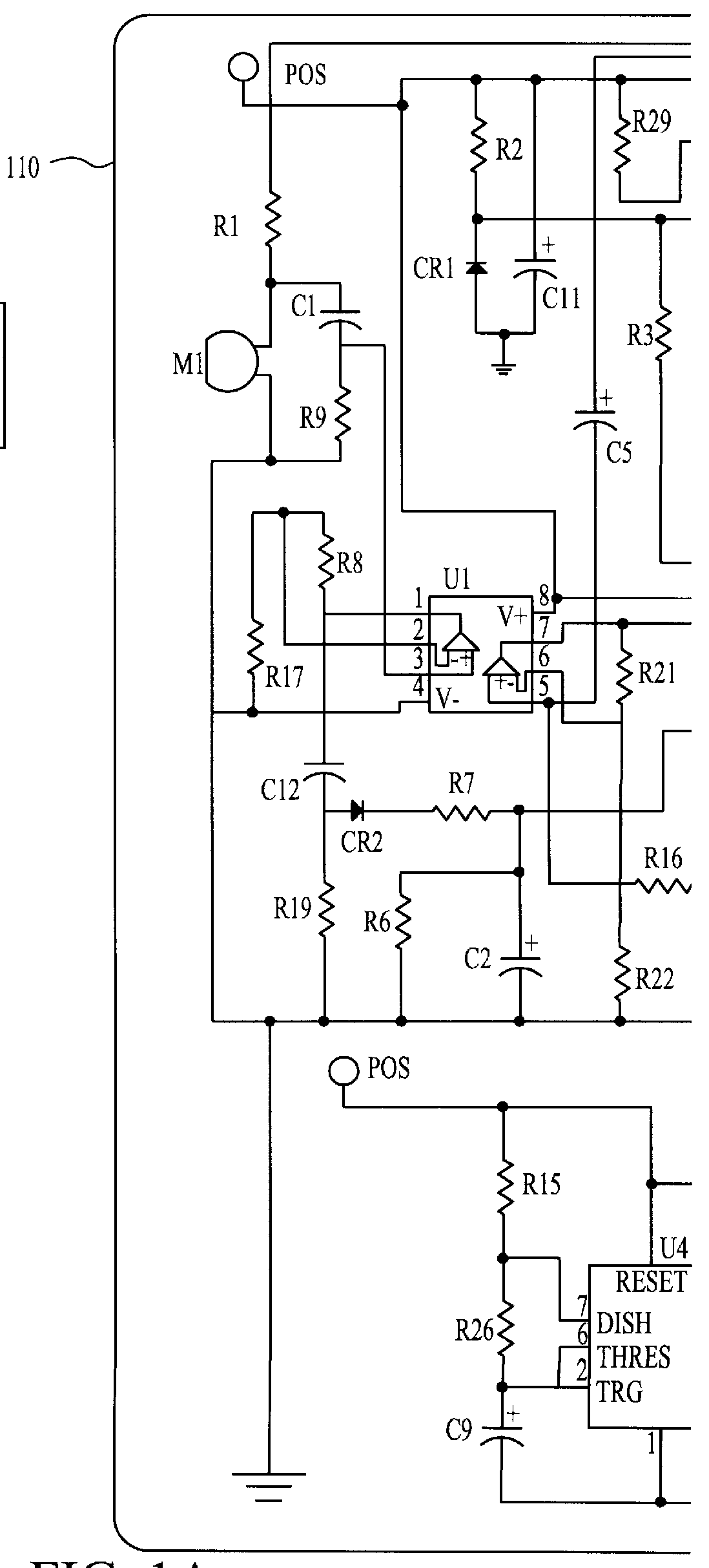
Referring now to the schematic diagrams, and more particularly to FIG. 1, there is shown a battery drain limitation device 110 attached between, for example, an automobile battery 111 and a vehicle load 112. The load 112, while shown as a single resistive load in FIG. 1, is in fact composed of a plurality of loads as further shown in FIG. 2 including, for example, clocks, radio memory and other small loads which normally are connected even when the vehicle is not in operation (Load 1 in FIG. 2), head lights and stop lights (Load 2 in FIG. 2), radio and dome or running lights (Load 3 in FIG. 2), and the starter motor (Load 4 in FIG. 2).

For any particular vehicle or equipment having a battery operated starter motor and an engine, when the electrical characteristics of the battery are considered in light of the power required by the starter motor to start the engine under anticipated operating conditions, there will be a threshold no load battery voltage at which the battery charge is ...


PUM


Abstract

A battery drain limitation circuit for use in engine powered vehicles and equipment which rely upon a battery to start the engine and also to operate accessories. When the engine is not running, the circuit disconnects the battery from all loads when battery charge, as measured by either one of two complementary means responsive to high and low drain rates, respectively, falls to a level below which the battery charge may not be sufficient to start the engine. High drain rates exaggerate battery voltage reduction below no load voltage levels, and are detected by a low cutoff voltage level after which the battery voltage recovers to reflect sufficient charge to start the engine. Battery dissipation from low drain rates is prevented by a long timing delay following detection of a high cutoff voltage level. The circuit is rendered inoperable if the engine is running, by means of a microphone which detects engine noise. The device is simple to install at the battery.

Description

1. Field of the InventionThe present invention generally relates to battery protection devices for use in engine powered vehicles and equipment which rely upon a battery to start the engine and, more particularly, to protective circuitry responsive to variation in the electrical characteristics of a battery due to different drain rates.2. Description of the Prior ArtThe battery used to start the engine in engine powered vehicles and equipment may be drained by the operation of associated electrical apparatus or by short circuits. The problem of preserving sufficient charge in the battery so that it is usable to start the engine has been variously resolved in the art. Conventional practice is to recharge the battery when the engine is running, so problem resolution focusses on drains which occur when the engine is not running. Common to such resolutions is the objective of detecting a battery discharge condition beyond which the battery may not be able to start the engine, and the ob...

Claims


Application Information

Patent Timeline
IPC IPC(8): H02J9/06H02J7/00
CPCH02J9/06H02J7/0031
Inventor RUND, LARRY D.HEWITT, RICHARD P.SIGAFOOS, STUART O.
Owner POWER TECHNICS
Why Eureka
Try Eureka