Hoist ring

a technology of hoist ring and ring body, which is applied in the field of hoist ring, can solve the problems of increasing the performance of side-pull hoist ring, reducing the cost, and unable to remove the bolt from the bushing of the post assembly without, and achieves the effects of easy disassembly in the field, easy manufacturing, and appearance of strength and integrity

Inactive Publication Date: 2000-05-30
JERGENS
View PDF13 Cites 61 Cited by
  • Summary
  • Abstract
  • Description
  • Claims
  • Application Information

AI Technical Summary

Benefits of technology

In accordance with another aspect of the present invention, the upper flange carried by the bolt is a separate washer held by the head of the bolt onto the top of the bushing. As the bolt is pushed into the bushing, the washer or upper flange engages the top of the bushing when the grooves, constituting the lock means, are in axial alignment. The same effect is accomplished when the upper flange is integral with the bolt. In this instance, the top of the bushing engages a cylindrical shoulder on the shank of the bolt to determine the assembled position of the post assembly with the locking grooves in axial alignment. In both of these instances, the bushing has a generally conical lead-in portion above the first cylindrical groove in the passageway of the bushing. The conical lead-in portion forms an angle with respect to the perpendicular axis of the post assembly so the spring element carried by the shank of the bolt is cammed inward into the groove in the bolt, which groove is deep enough to accommodate the movement of the shank axially within the bushing. When the two grooves are axially aligned, in the preferred embodiments with the top of the bushing engaging either the washer or shoulder on the shank, the spring element relaxes into the groove of the passageway. This groove is fairly shallow. The spring element forms an interference fit between the shank and bushing with the spring element held in its locked position. The bolt can not be removed from the bushing of the post assembly without destruction of the spring element, which element is hardened spring steel and not easily sheared. Thus, the post assembly has a lower flange with a large contact area engaging the load being lifted and a hidden locking mechanism between the shank of the bolt and the passageway of the bushing to hold the bolt and bushing locked together after assembly by the manufacturer of the hoist ring.
In accordance with another aspect of the present invention, the clevis of the side-pull hoist ring is formed from a bent sheet steel, an extruded steel, steel bar stock or an extruded steel element machined to produce the U-shaped configuration. By producing the clevis in this manner, the disadvantages of cast clevis and the uncertainty of rejection rates is overcome. In addition, the improved hoist ring including the novel locked bushing and bolt. This concept substantially decreases the cost and increases the performance of a side-pull hoist ring. As a secondary application, the invention is adapted for use in a center-pull snap hoist ring even though this is not the preferred implementation of the invention.
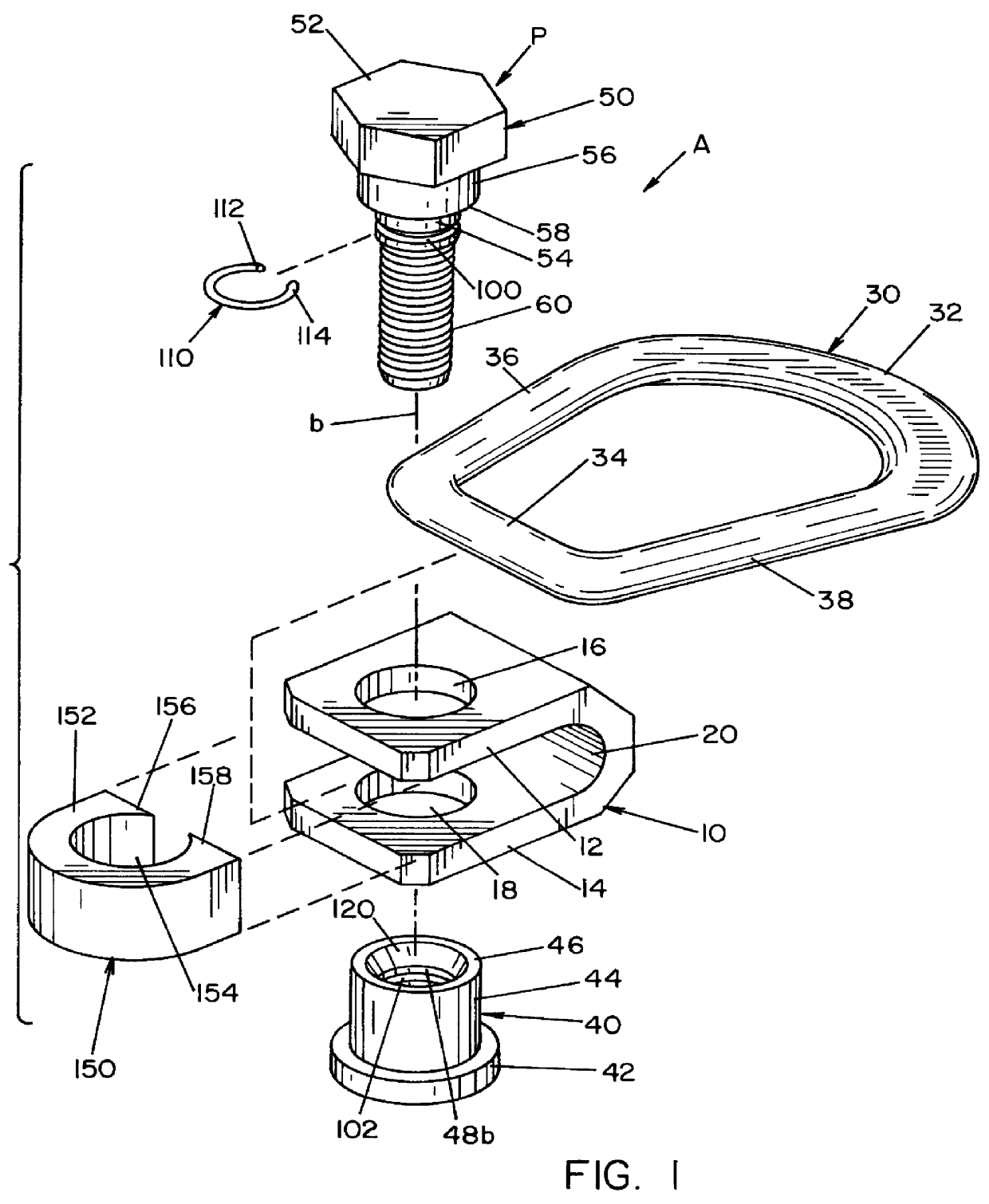
In accordance with another aspect of the present invention, there is provided an improvement in a side-pull hoist ring of the type fixed into a threaded bore on the outer surface of a heavy load to be carried. The side-pull hoist ring has a load carrying ring and a support member mounted for rotation about an axis perpendicular to the outer surface of the load. The hoist ring includes a post assembly extending through the support member and fixedly engaging the load being carried. In this manner, the side-pull hoist ring can rotate 360.degree.. The improvement in this type of side-pull hoist ring includes constructing the post assembly with a support bushing having a lower load bearing flange which is relatively large in diameter. A bolt receiving passageway in the bushing is coaxial with the perpendicular rotational axis of the support member. The bolt extends through the passageway into the threaded bore holding the side-pull hoist ring onto the load. The bolt has a head carrying a large upper flange that coacts with the lower flange to capture the support member between the flanges. The support member is a generally U-shaped clevis with aligned holes receiving the post assembly and a bight portion receiving the continuous load ring of the hoist ring. By providing a bushing with a large area for a side-pull hoist ring, the lever arm created when the ring is pulled perpendicularly around the corner of a die is reduced. This substantially reduces the forces created on the side-pull hoist ring. In accordance with still a further aspect of the present invention there is provided a clevis for a side-pull hoist ring, which clevis is formed as a bent piece of steel, extruded steel or bar stock. The primary object of the present invention is the provision of an improved hoist ring, which hoist ring has a post assembly providing a large diameter support flange and a locking mechanism for permanently locking the bolt and bushing forming the post assembly.
Another object of the present invention is the provision of an improved hoist ring, as defined above, which hoist ring is permanently assembled by the manufacturer and reduces the reactive forces when the hoist ring is maneuvered into various positions.
Another object of the present invention is the provision of an improved hoist ring, as defined above, which hoist ring is economical to manufacture, requires a lesser amount of part inventory and has an appearance of strength and integrity.
A further object of the present invention is the provision of an improved hoist ring, as defined above, which hoist ring has no exposed snap rings allowing easy disassembly in the field.

Problems solved by technology

The bolt can not be removed from the bushing of the post assembly without destruction of the spring element, which element is hardened spring steel and not easily sheared.
This concept substantially decreases the cost and increases the performance of a side-pull hoist ring.

Method used


Image

  • Hoist ring
  • Hoist ring
  • Hoist ring

Examples


Embodiment Construction

Referring now to the drawings wherein the showings are for the purpose of illustrating the preferred embodiment only and not for the purpose of limiting same, FIGS. 1-4 show a side-pull hoist ring A constructed in accordance with the preferred embodiment of the invention and FIGS. 12 and 13 illustrate how hoist ring A is secured in a threaded bore B perpendicular to the surface S of a heavy load L to be lifted in accordance with standard use of hoist rings. Ring A includes a rotatable support member 10 in the form of a U-shaped clevis with generally parallel legs 12, 14 having holes 16, 18 for mounting the clevis to rotate about axis b perpendicular to surface S. Clevis 10 includes an outboard bight 20 that receives one end of continuous load ring 30. The load ring can be generally circular, but is illustrated as elongated in the preferred embodiment. This elongated continuous load ring includes a larger cross sectioned enlarged end 32 and a generally straight smaller end 34 that is...


PUM


Abstract

In a side-pull hoist ring having a load carrying ring, a clevis pivotally supporting the load carrying ring for rotation about a first axis and a post assembly extending through the clevis and fixedly engageable with a threaded bore on a load for allowing 360 DEG rotation of the clevis about a second axis generally perpendicular to the load. The post assembly includes a lower support bushing with a large diameter lower load bearing flange and a bolt receiving passageway coaxial with the second axis; a bolt extending through the passageway into the threaded bore of the load where the bolt has a head carrying an upper flange member coacting with the lower flange to capture the clevis and a shank. There is a first cylinder groove in the passageway and a second cylindrical groove around the shank. The grooves are axially aligned when the lower flange and the upper flange capture the clevis. An arcuate spring element having a collapsed shape generally retained in the second groove and a relaxed shape bottomed out in the first groove and extending between the first and second grooves prevents non-destructive axial removal of the bolt from the bushing. The clevis is formed from extruded steel, bar stock or a steel plate.

Description

BACKGROUND OF INVENTIONThe present invention relates to a hoist ring of the type used to lift a variety of heavy loads or objects, such as die sets and molds; however, the invention has much broader applications and may be used for a variety of applications where it is necessary to secure a ring to a structure, either to lift the structure or to hold down a structure such as containers, air crafts, air vehicles, boats, etc. Through the years, a large number of hoist devices has been developed which allow for a ring to be connected to the hook of a hoist wherein the ring pivots and swivels for the purpose of automatically adjusting the disposition of the ring with respect to the force being applied to the hoist during the lifting procedure. Such devices are found in patents incorporated by reference herein. Most of these devices are center-pull hoist rings where a post assembly extends through and allows 360.degree. rotation of a support member. The rotating support member carries th...

Claims


Application Information

Patent Timeline
Patent Type & Authority Patents(United States)
IPC IPC(8): B66C1/62B66C1/66
CPCB66C1/66Y10T403/32213Y10T403/32975
Inventor FULLER, HARRY P.KLINGENBERG, JAMES C.
Owner JERGENS
Why Eureka
Try Eureka