Electroplating workpiece fixture having liquid gap spacer

a workpiece fixture and liquid gap technology, applied in the field of electroplating methods and apparatuses, can solve the problems of causing a defective part, causing undesired buildup of plated metal over the insulating spacer between the thief and the substrate, and causing a problem of metal distribution on the substra

Inactive Publication Date: 2000-06-06
NOVELLUS SYSTEMS
View PDF31 Cites 191 Cited by
  • Summary
  • Abstract
  • Description
  • Claims
  • Application Information

AI Technical Summary

Problems solved by technology

Moreover, the increasing interconnect current density accompanying the decreasing line and via dimensions is a source of reliability concern, especially in aluminum (Al) based metallurgy, the backbone of present day chip wiring.
In interconnect metallization schemes, the uniformity of metal distribution on the substrate has been a source of concern.
The later arrangement tends to produce the desired metal uniformity on the workpiece or substrate of interest; however, during plating, an undesired buildup of plated metal over the insulating spacer between the thief and the substrate often occurs.
The buildup of plated metal over the thief / substrate insulating spacer undesirably shorts the thief to the workpiece.
The bridging of the thief to the workpiece or wafer distorts the desired metal distribution profile on the workpiece or wafer, thus producing a defective part, and further requiring a rework operation.
Such a periodic replacement of thief / workpiece cathode assembly results in losses due to equipment down time, and the cost / expense of frequent inspection of the thief / wafer isolator for conditions of undesired metal bridging.

Method used


Image

  • Electroplating workpiece fixture having liquid gap spacer
  • Electroplating workpiece fixture having liquid gap spacer
  • Electroplating workpiece fixture having liquid gap spacer

Examples


Embodiment Construction

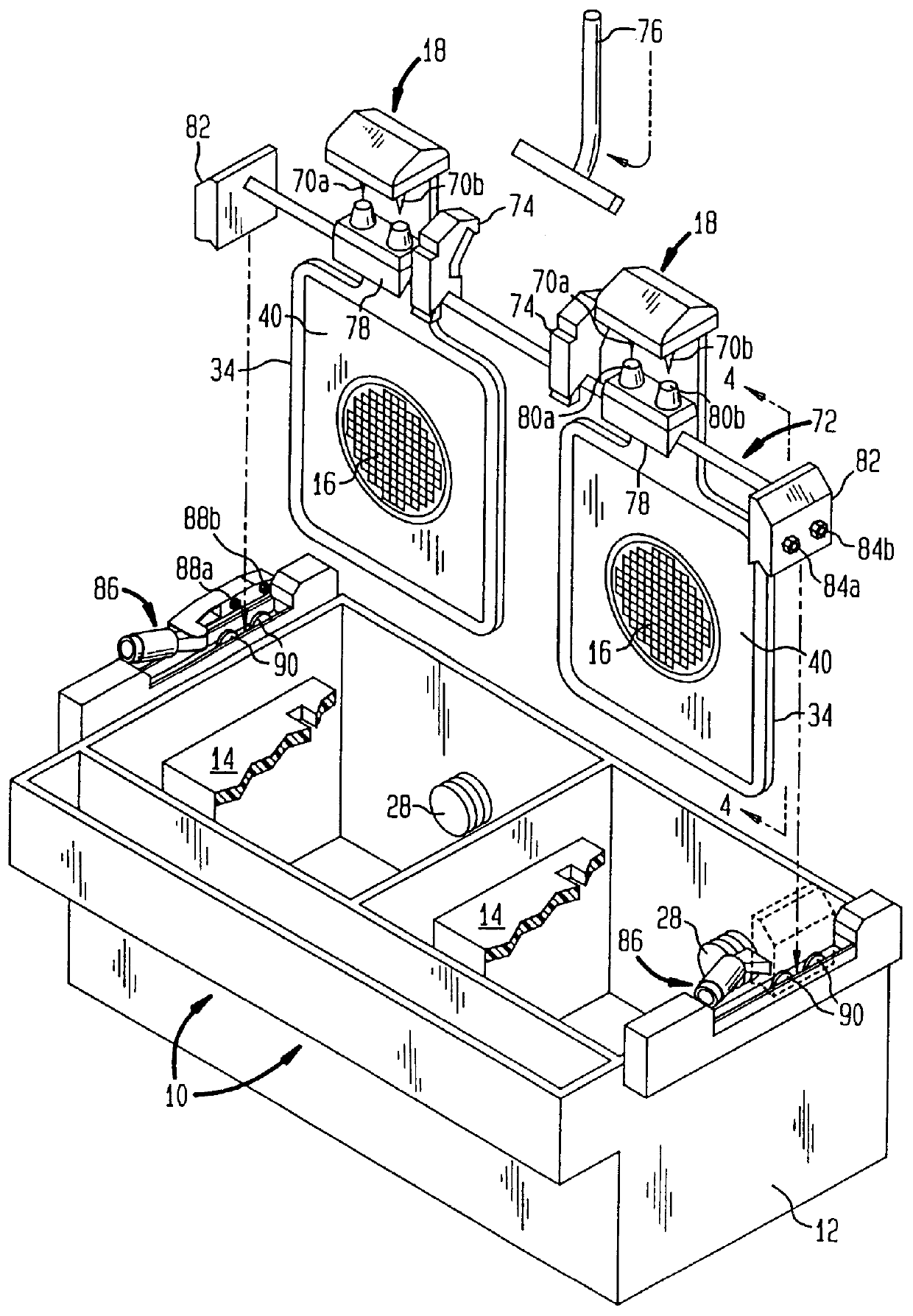
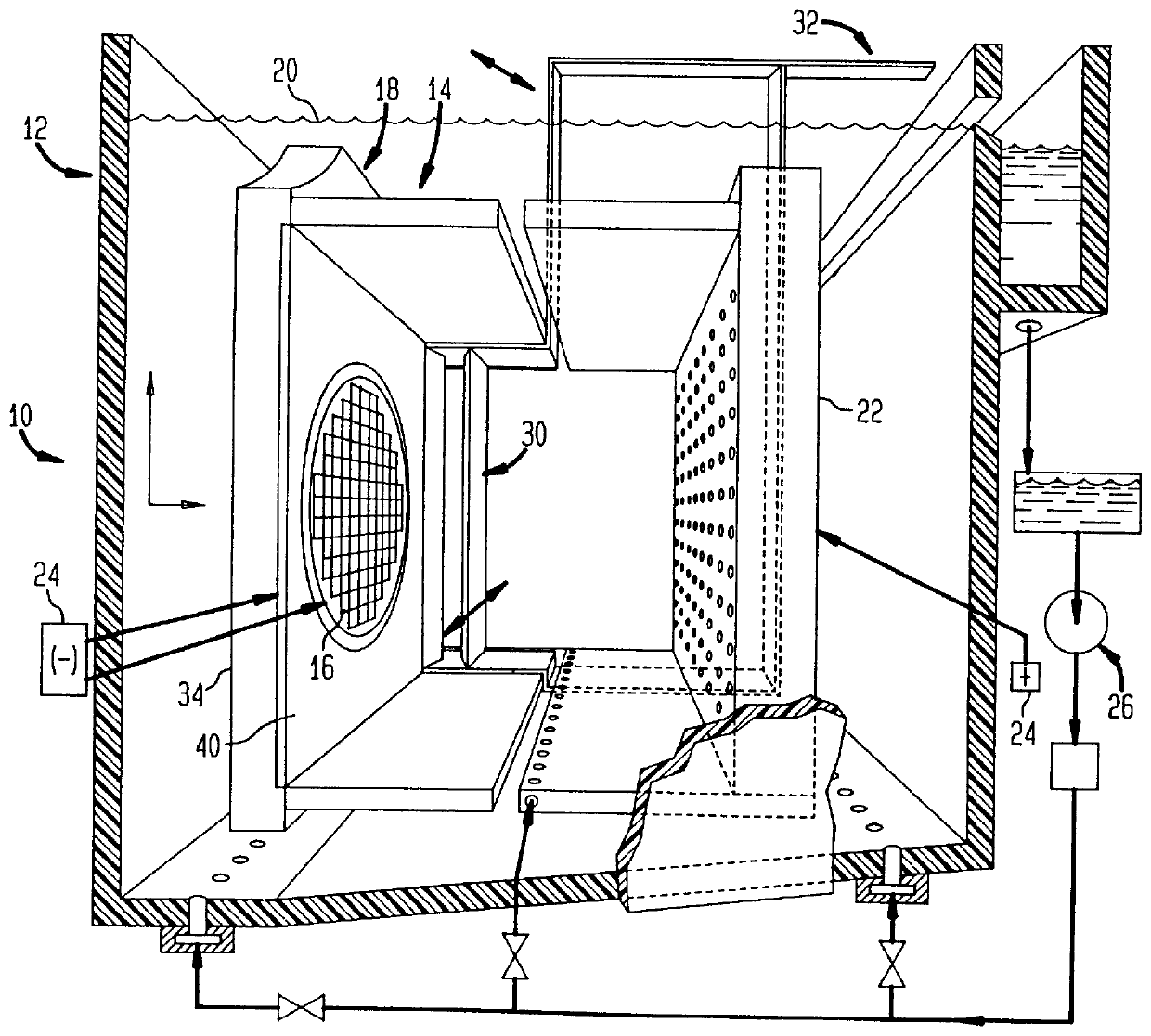
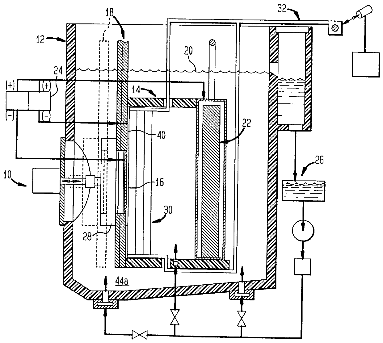
To assist in the discussion of the present invention, the invention shall be described with respect to vertical paddle plating cells (VPPCs) 10, such as schematically illustrated in FIG. 1. It should be understood that the present invention is also applicable to non-vertical plating cells. Plating cells 10 have a common, bifurcated housing 12. Each of the cells 10 includes an identical inner cell 14 configured for use in electroplating a flat workpiece article 16. The workpiece 16 may take any conventional form that requires uniform plating thickness thereon such as recording heads, packaging modules, or integrated circuits typically used in electronic devices or computers. In the exemplary embodiment illustrated, the workpiece 16 is a flat, circular wafer having a substantial number of individual integrated circuit (IC) chip patterns arranged suitably thereon. In one electroplating process, it is desired to electrodeposit on the IC chips a uniformly thick metal, for example. In a f...


PUM

PropertyMeasurementUnit
widthaaaaaaaaaa
perimeteraaaaaaaaaa
perimeteraaaaaaaaaa

Abstract

A fixture for supporting a workpiece during electroplating of a metal upon the workpiece in a conductive electroplating bath includes a non-conductive frame member for receiving the workpiece therein. The fixture further includes a current distribution means having a plurality of contacts. The plurality of contacts is disposed inwardly for providing an equally distributed electrical contact with an outer perimeter region of the workpiece. The workpiece is supported between the frame member and the current distribution means. Lastly, a thief electrode is perimetrically disposed about the workpiece and spaced a prescribed distance from the workpiece by a gap region. During plating of a metal upon the workpiece, the gap region between the thief and the workpiece is filled with the conductive electroplating bath. An electroplating apparatus having a fixture for supporting a workpiece during an electroplating process and a method of supporting the workpiece to be electroplated are also disclosed.

Description

1. Field of the InventionThis invention relates generally to a method and apparatus for electroplating and, more particularly, to a method and apparatus for holding a workpiece during electroplating with copper or other metals, for example, electroplating of semiconductor wafers.2. Discussion of the Related ArtTo meet the demands for higher and higher circuit speed in ultra large scale integrated (ULSI) circuit devices, it has become imperative to reduce the size of wiring structures in ULSI devices. For example, with respect to devices in any given dielectric film, as clock frequencies increase and as interconnect ground rules decrease, on-chip resistance-capacitance (RC) time delays increase. The restraints imposed by the increased RC time constants, becomes one of the critical impediments to achieving higher and higher circuit speeds. Moreover, the increasing interconnect current density accompanying the decreasing line and via dimensions is a source of reliability concern, espec...

Claims


Application Information

Patent Timeline
Patent Type & Authority Patents(United States)
IPC IPC(8): C25D7/12H01L21/288H01L21/02
CPCC25D7/12C25D17/06C25D17/001H01L21/2885C25D7/123
Inventor UZOH, CYPRIAN E.
Owner NOVELLUS SYSTEMS
Why Eureka
Try Eureka