Chemical oxygen iodine laser gain generator system

Inactive Publication Date: 2000-06-06
THE BOEING CO
View PDF14 Cites 54 Cited by
  • Summary
  • Abstract
  • Description
  • Claims
  • Application Information

AI Technical Summary

Benefits of technology

It is therefore a principal object of the present invention to provide a COIL ga

Problems solved by technology

The lower the reactor pressure, the lower the vacuum pressure must be, leading to a larger and more costly vacuum system.
The major disadvantage of higher Mach numbers is the impact on the vacuum system needed to operate the laser.
Direct substitution of nitrogen diluent for the usual helium diluent in a C

Method used


Image

  • Chemical oxygen iodine laser gain generator system

Examples


Embodiment Construction

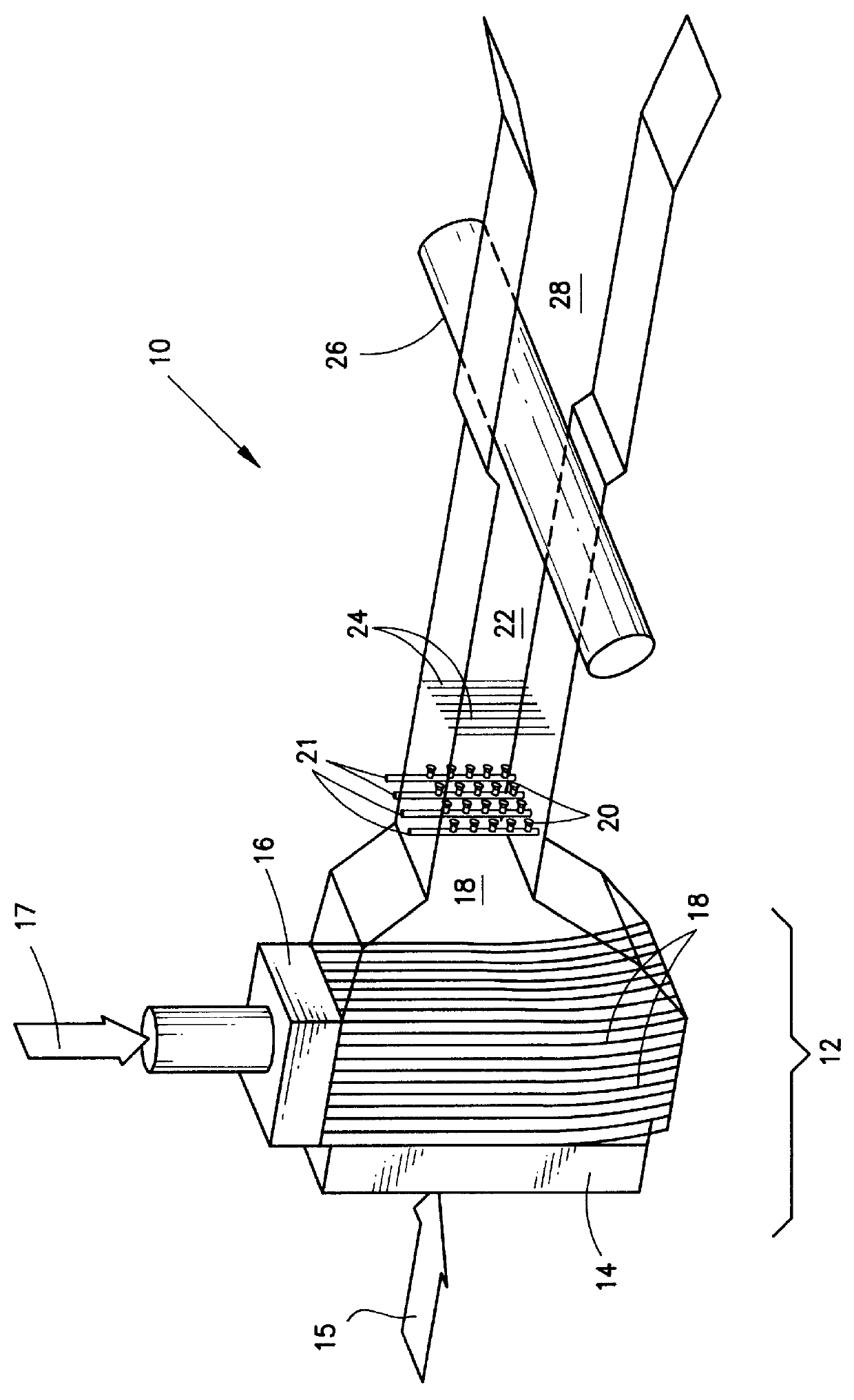
specific example of the subject system would include a reactor at 0.4 psia pressure flowing 1 gram mole per second of chlorine and 10 liters per second of BHP. The BHP would be flowed into the reactor through about 12000 very small orifices, creating 12000 jets of liquid BHP. Very little of the BHP would be reacted as it flows through the reactor. Residual BHP is drained continuously from the bottom of the reactor to be repeatedly recirculated through the reactor. The reactor would react approximately 90% of the chlorine, producing 0.9 moles per second of oxygen, of which about 60% would be in the singlet delta state, the remainder in the triplet sigma (ground) state. The mixture of oxygen and residual chlorine would approach the nozzle array at approximately Mach =0.4 and then accelerate to Mach=1 as it passes through the interstices between the array of nozzles. The nozzles, on approximately 1 / 2 inch centers, would flow a mixture of 5-gram moles per second of 373K stagnation tempe...


PUM


Abstract

The COIL gain generator system includes a reactor for producing singlet delta oxygen and a mechanism for mixing high momentum diluent with the singlet delta oxygen and with iodine for producing a high momentum, low static temperature mixture of the singlet delta oxygen, diluent and iodine. The singlet delta oxygen and the iodine react to produce excited iodine atoms which can lase efficiently due to the low static temperature and can, after lasing, recover to high pressure in a diffuser due to the high momentum of the mixture. This provides the capability of using a chemical pump which allows a completely sealed system with no outside exhaust.

Description

1. Field of the InventionThe present invention relates to chemical oxygen iodine laser's (COIL) and more particularly to a coil gain generator which provides enhanced efficiency, flow capacity and pressure recovery.2. Description of the Related ArtCOIL (Chemical Oxygen Iodine Laser) devices produce laser optical energy from energy stored in a form of oxygen known as singlet delta oxygen, (O.sub.2 (.sup.1 .DELTA.)). The O.sub.2 (.sup.1 .DELTA.) is typically produced in a gas liquid contact reactor (see e.g., U.S. Pat. No. 5,658,535, U.S. Pat. No. 5,624,654 and U.S. Pat. No. 5,516,502) from gaseous chlorine (Cl.sub.2) and liquid basic hydrogen peroxide (BHP). The BHP is a mixture of hydrogen peroxide and a strong base such as KOH. The gaseous Cl.sub.2 is absorbed into the BHP and reacts to form the highly energetic O.sub.2 (.sup.1 .DELTA.) which diffuses out of the BHP into the gaseous phase. The O.sub.2 (.sup.1 .DELTA.) has a strong tendency to be quenched by pooling the energy of tw...

Claims


Application Information

Patent Timeline
IPC IPC(8): C01B11/22C01B11/00H01S3/22H01S3/14
CPCC01B11/22H01S3/2215Y10S372/701
Inventor DICKERSON, ROBERT A.
Owner THE BOEING CO
Why Eureka
Try Eureka